| CPC B05C 5/0237 (2013.01) [B05C 5/001 (2013.01); F16K 31/1221 (2013.01); F16K 31/124 (2013.01)] | 57 Claims |

|
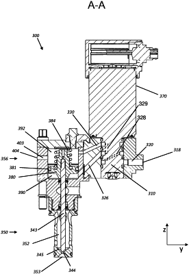
1. A dispensing assembly for dispensing a liquid onto a substrate, the dispensing assembly comprising:
a housing configured to receive the liquid to be dispensed;
a valve stem disposed in the housing and having a first configuration in which the liquid is allowed to exit the housing and a second configuration in which the liquid is prevented from exiting the housing;
a control valve configured to receive pressurized air from a pressurized air source, the control valve being movable between a first position and a second position;
an exhaust passage defined on the housing and having a predetermined cross-sectional area, the exhaust passage being configured to receive the pressurized air therein;
a first chamber;
a first channel being disposed between the first chamber and the control valve, the first channel being in fluid communication with the first chamber, and the first channel being in fluid communication with the control valve when the control valve is in the first position;
a second chamber that is separate from the first chamber and is in fluid communication with the exhaust passage; and
a second channel that is disposed between the second chamber and the control valve,
wherein when the control valve is in the first position, the pressurized air is configured to act on the valve stem to cause the valve stem to move to the first configuration or to the second configuration, and when the control valve is in the second position, the pressurized air acting on the valve stem is configured to be moved into the exhaust passage and out of the dispensing assembly through the exhaust passage,
wherein when the control valve is in the first position, the control valve is configured to receive the pressurized air from the pressurized air source and to discharge the pressurized air into the first channel, whereby the control valve is configured to be in fluid communication with the first chamber and configured to direct the pressurized air to the first chamber,
wherein when the control valve is in the second position, the control valve is configured to be in fluid communication with the second chamber, and is further configured to direct the pressurized air from the first chamber to the second chamber via the second channel,
wherein the exhaust passage is configured to fluidly communicate with the second chamber, and
whereby when the control valve is in the second position, the pressurized air that is present in the first chamber is permitted to move through the first channel, through the control valve, through the second channel, and into the second chamber.
|