| CPC H02P 29/10 (2016.02) [F04D 25/06 (2013.01); H02P 7/22 (2013.01); H02P 7/29 (2013.01); H02P 29/40 (2016.02)] | 20 Claims |

|
1. A handheld blower comprising:
a housing including a suction port; a first discharge port; and an attachment fitting portion, the suction port and the first discharge port communicating an inside of the housing with an outside of the housing, the first discharge port having an opening area of a first magnitude, the attachment fitting portion being configured to detachably attach an attachment to the first discharge port, the attachment (i) being in the form of a nozzle, (ii) including a second discharge port, and (iii) being configured to receive an airflow discharged through the first discharge port and to discharge the airflow through the second discharge port, the second discharge port having an opening area of a second magnitude, and the second magnitude being smaller than the first magnitude;
a motor in the housing;
a fan (i) in the housing and (ii) configured to be rotationally driven by the motor to thereby generate the airflow to be discharged through the first discharge port;
a trigger configured to be pulled by a user of the blower;
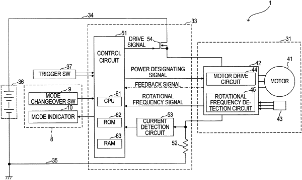
a control circuit programmed to:
set an output duty ratio based on a trigger level, wherein the trigger level corresponds to a pulled distance of the trigger; and
output a power designating signal having the output duty ratio; and
a motor drive circuit configured to:
receive the power designating signal;
deliver, to the motor, an electric power having a magnitude in accordance with the output duty ratio of the power designating signal received; and
perform a constant power control that maintains the magnitude of the electric power delivered to the motor at a magnitude corresponding to the output duty ratio.
|