| CPC H01M 50/503 (2021.01) [H01M 50/209 (2021.01); H01M 50/50 (2021.01); H01M 50/505 (2021.01); H01M 2220/20 (2013.01)] | 3 Claims |

|
1. A power storage component module comprising:
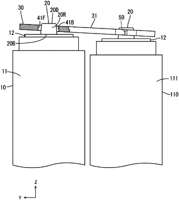
a first power storage component and a second power storage component a bus bar connecting the first power storage component and the second power storage component to one another;
positioning boss positioning bosses, each of which is provided on a respective electrode included in each of the first power storage component and the second power storage component, each of the positioning bosses protruding upward and including a base end and a distal end having a diameter less than a diameter of the base end;
two through holes opening in the bus bar, wherein
the bus bar is placed on the positioning bosses and a hole edge, of a respective one of the two through holes, is disposed around a respective one of the positioning bosses between the base end of the respective one of the positioning bosses and the distal end of the respective one of the positioning bosses in a vertical direction, and
the hole edge is joined to the respective one of the positioning bosses to define a respective joint;
wherein the positioning bosses are arranged in a predefined direction, the two through holes are arranged in the predefined direction, each of the two through holes has an oval shape elongated in the predefined direction, and in a direction perpendicular to the predefined direction, a diameter of each of the two through holes is less than a diameter of the base end of the respective one of the positioning bosses and greater than a diameter of the distal end of the respective one of the positioning bosses; and
wherein the respective joint includes a first joint and a second joint, and the first joint and the second joint are arranged with the respective one of the positioning bosses between the first joint and the second joint in the direction perpendicular to the predefined direction, and
wherein the first joint and the second joint are aligned in a direction that is orthogonal to both the predefined direction and the protruding direction of the respective one of the positioning bosses.
|