| CPC H01L 27/0808 (2013.01) [H01L 29/66174 (2013.01); H01L 29/93 (2013.01); H10B 99/00 (2023.02)] | 10 Claims |
|
1. An integrated circuit structure, comprising:
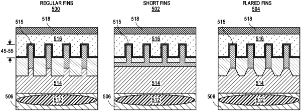
a plurality of fins extending above a surface of a substrate along a first direction, the plurality of fins spaced apart from one another;
a gate over the plurality of fins, the gate along a second direction substantially orthogonal with the first direction;
an insulating layer that surrounds and is in contact with respective ones of the plurality of fins in-between the substrate and the gate;
an N-type well located in the substrate below the plurality of fins; and
an N-type doping in the substrate between the plurality of fins and the N-type well, the N-type doping extending vertically from the substrate to only a portion a height of the respective ones of the plurality of fins that extend above the surface of the substrate and below the gate, wherein the N-type doping has a doping concentration of 2e18-7e18.
|