| CPC G06F 3/0421 (2013.01) [G02B 5/0226 (2013.01); G02B 5/305 (2013.01); G02B 6/0051 (2013.01)] | 18 Claims |

|
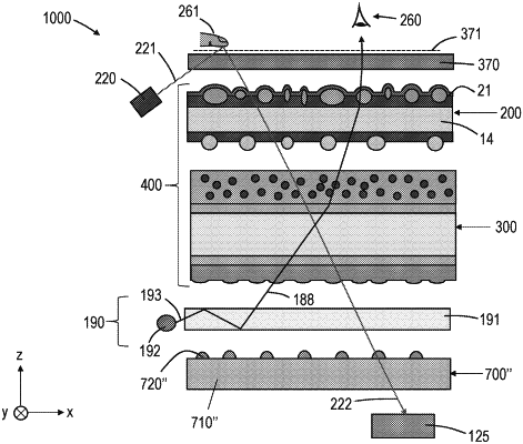
1. A display system for sensing a finger of a user applied to the display system, the display system comprising:
a display panel configured to generate an image for viewing by the user;
a sensor for sensing the finger of the user disposed proximate the display panel;
a sensing light source configured to emit a first light having a first wavelength W1 toward the finger of the user, the sensor configured to receive and detect at least a portion of the first light reflected by the finger; and
a reflective polarizer disposed between the display panel and the sensor and comprising a plurality of polymeric layers numbering at least 50 in total, such that for a substantially normally incident light, an optical transmittance of the reflective polarizer versus wavelength for a first polarization state comprises a band edge, wherein:
a best linear fit to the band edge correlating the optical transmittance to the wavelength at least across a wavelength range where the optical transmittance along the band edge increases from about 10% to at least about 70% has a slope of greater than about 2.5%/nm; and
for a first wavelength range extending from a smaller wavelength L1 to a greater wavelength L2 and comprising W1, 30 nm≤L2−L1≤50 nm, L1 greater than and within about 20 nm of a wavelength L3 corresponding to an optical transmittance of about 50% along the band edge, the optical transmittance has an average of greater than about 75%,
wherein for the substantially normally incident light and a predetermined wavelength range, the reflective polarizer has an average optical reflectance of at least 70% for the first polarization state and an average optical transmittance of at least 40% for an orthogonal second polarization state.
|