| CPC F15B 15/1433 (2013.01) [F15B 11/0413 (2013.01); F15B 15/204 (2013.01); F15B 15/22 (2013.01); F15B 11/06 (2013.01); F15B 2211/30505 (2013.01); F15B 2211/329 (2013.01); F15B 2211/355 (2013.01); F15B 2211/40515 (2013.01); F15B 2211/40584 (2013.01); F15B 2211/40592 (2013.01); F15B 2211/7053 (2013.01); F15B 2211/75 (2013.01); F15B 2211/8855 (2013.01)] | 6 Claims |

|
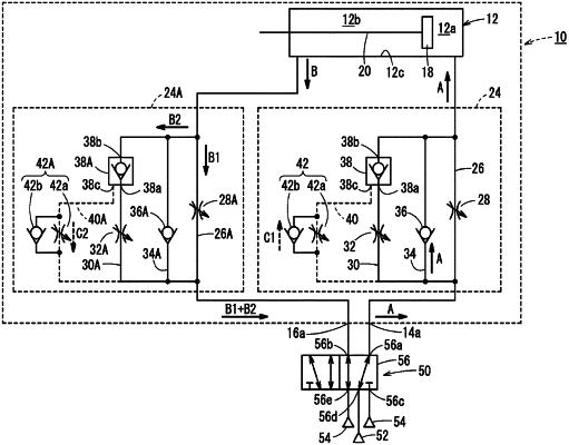
1. An air cylinder, comprising:
a cylinder tube in which a cylinder chamber is formed;
a head cover configured to close one end of the cylinder tube;
a rod cover configured to close another end of the cylinder tube;
a piston configured to slide in the cylinder chamber;
a piston rod having one end connected to the piston;
a port provided in each of the head cover and the rod cover; and
a flow rate controller incorporated into at least one of the head cover or the rod cover,
wherein the flow rate controller includes:
a first flow path configured to allow communication between the port and the cylinder chamber;
a first flow rate control valve disposed in the first flow path;
a second flow path disposed in parallel with the first flow path;
a second flow rate control valve disposed in the second flow path;
a pilot check valve disposed in series with the second flow rate control valve in the second flow path;
a pilot air flow path, one end of which with the first flow path between the first flow rate control valve and the port, and with the second flow path between the second flow rate control valve and the port, and another end of which is connected to a pilot port of the pilot check valve; and
a third flow rate control valve disposed midway along the pilot air flow path and configured to supply and discharge pilot air to and from the pilot check valve, and
wherein, depending on a pressure of the pilot air, the pilot check valve switches between a state allowing passage of exhaust air discharged from the cylinder chamber, and a state preventing the passage of the exhaust air.
|