| CPC F02M 61/167 (2013.01) [F02M 2200/03 (2013.01); F02M 2200/85 (2013.01)] | 20 Claims |

|
1. A fuel injector assembly comprising:
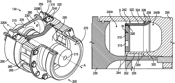
a fuel gallery that is annular around an injector axis and includes an inner diameter and an outer diameter;
an inner arm that is annular around the injector axis and positioned within the fuel gallery, wherein the inner arm includes a first axial portion, and wherein an inner diameter of the first axial portion is greater than the inner diameter of the fuel gallery, such that a first space exists between the first axial portion and a radially inner surface of the fuel gallery;
an outer arm that is annular around the injector axis and positioned within the fuel gallery, wherein the outer arm includes a second axial portion, wherein an outer diameter of the second axial portion is less than the outer diameter of the fuel gallery, such that a second space exists between the second axial portion and a radially outer surface of the fuel gallery; and
a distributor plate that is annular around the injector axis and positioned between the first axial portion and the second axial portion to divide the fuel gallery into a forward region and an aft region, wherein a radially inner edge of the distributor plate is bonded to the first axial portion, and wherein a radially outer edge of the distributor plate is bonded to the second axial portion.
|