| CPC A61B 18/14 (2013.01) [A61B 1/00087 (2013.01); A61B 1/00096 (2013.01); A61B 2017/0023 (2013.01); A61B 2017/00424 (2013.01); A61B 2018/00202 (2013.01); A61B 2018/00517 (2013.01); A61B 2018/00601 (2013.01); A61B 2018/1475 (2013.01); A61B 2217/007 (2013.01); A61B 2218/002 (2013.01)] | 19 Claims |

|
1. A device comprising:
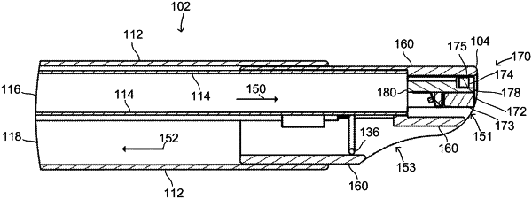
a shaft portion that extends along a longitudinal axis, the shaft portion comprising:
an outer sheath,
an inner shaft provided within the outer sheath,
an optical assembly provided at a distal end of the inner shaft, the optical assembly including a light source and an imaging sensor; and
a handle portion that is coupled to a proximal end of the shaft portion,
wherein a first channel that extends along the longitudinal axis is defined by one or both of the outer sheath and the inner shaft, the first channel providing a first flow path between the proximal end of the shaft portion and a first opening provided at a distal end of the shaft portion, the first opening being provided between the optical assembly and the inner shaft to partially surround the optical assembly on three sides,
wherein a second channel that extends along the longitudinal axis is defined by one or both of the outer sheath and the inner shaft, the second channel providing a second flow path between the proximal end of the shaft portion and a second opening provided at the distal end of the shaft portion, the second flow path being distinct from the first flow path,
wherein the optical assembly is provided at a distal end of the first channel to thereby partially block and divert the first flow path around the optical assembly to the first opening, the first opening and the optical assembly being configured to direct turbulent fluid flow (i) around the light source and the imaging sensor and (ii) across a distal surface of the optical assembly, wherein a surgical tool is provided in the second channel; and
wherein the first channel is configured to direct fluid into contact with a proximal surface of the optical assembly, the proximal surface facing the proximal end of the shaft portion.
|