| CPC H02M 3/156 (2013.01) [H02M 1/0009 (2021.05); H02M 1/0058 (2021.05); H02M 3/158 (2013.01); H05B 45/375 (2020.01)] | 17 Claims |

|
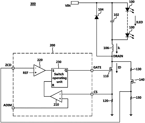
1. A switch control circuit, comprising:
a load, an inductor, a first switch, and a sensing resistor connected in series with an input power source terminal;
a sensing circuit, comprising a first resistor, a second switch, and a second resistor connected in series between a drain terminal of the first switch and a ground terminal, wherein the sensing circuit is configured to sense when current flowing through the inductor is equal to 0 A (Zero ampere);
a first comparator, configured to compare a sensing voltage with a load current setting voltage;
a second comparator, configured to compare a drain sensing voltage with a predetermined reference voltage; and
a switch operating unit, configured to control the first switch based on an output signal of the first comparator and an output signal of the second comparator,
wherein the second comparator is configured to apply the output signal of the second comparator to the switch operating unit to turn on the first switch when the drain sensing voltage is less than the predetermined reference voltage,
the drain sensing voltage senses a drain voltage of the first switch between the second switch and the second resistor of the sensing circuit, and
the second switch is configured to turn off to prevent current consumption when the switch control circuit is not being operated.
|