| CPC H02K 5/225 (2013.01) [H01R 9/223 (2013.01); H02K 7/006 (2013.01); B60R 16/0215 (2013.01)] | 4 Claims |

|
1. A drive device comprising:
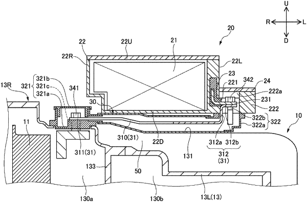
a drive unit including a rotary electric machine and a drive unit case that houses the rotary electric machine;
a control unit including a control device configured to control the rotary electric machine and a control unit case that houses the control device; and
a connection unit including a connection line that electrically connects the rotary electric machine and the control device, wherein
the connection line includes:
an extending portion extending in a predetermined direction;
a rotary-electric-machine-side connection terminal portion provided at one end portion of the extending portion and electrically connected to the rotary electric machine; and
a control-device-side connection terminal portion provided at another end portion of the extending portion and electrically connected to the control device,
the drive unit case has an outer peripheral surface extending in a circumferential direction of a rotation axis line of the rotary electric machine,
the control unit is disposed at a position facing the outer peripheral surface of the drive unit case,
a space portion is provided between the outer peripheral surface of the drive unit case and the control unit, and
the connection unit is provided such that the connection line electrically connects the rotary electric machine and the control device through the space portion.
|