| CPC H02K 19/103 (2013.01) [A47L 9/22 (2013.01); H02K 1/02 (2013.01); H02K 1/146 (2013.01); H02K 1/246 (2013.01); H02K 7/14 (2013.01)] | 6 Claims |

|
1. A vacuum cleaner comprising a drive motor comprising:
a shaft configured to be rotatable;
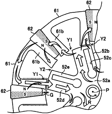
a rotor rotatably coupled to the shaft and configured to be rotatable about the shaft, the rotor including a plurality of salient poles that protrude in a radial direction from the shaft; and
a stator positioned to surround the rotor with a first air gap interposed therebetween and arranged along a circumferential direction of the rotor,
wherein the stator includes:
a stator core having a back yoke and a plurality of teeth extending inwardly from the back yoke; and
a plurality of coils respectively installed around the plurality of teeth,
wherein the stator core includes a plurality of element cores and a plurality of magnets,
wherein each of the plurality of salient poles includes:
a second air gap, and first and second magnetic circuit located on opposite sides of the second air gap,
wherein the first magnetic circuit is located on a forward side of a rotational direction of the rotor among the opposite sides of the second air gap, and
wherein the first magnetic circuit has a cross sectional area larger than a cross sectional area of the second magnetic circuit for a cross-section perpendicular to a protruding direction of each of the salient poles,
wherein each of the plurality of element cores is formed by stacking a plurality of U-shaped iron plates formed of magnetic material and including a yoke element in an arc shape and a pair of teeth elements axially extending from both ends of the yoke element in opposing shapes, and
the yoke element forms a portion of the back yoke, and each of the pair of teeth elements forms a side portion of each of the plurality of teeth,
wherein the plurality of magnets are arranged with same magnetic poles opposite to each other in the circumferential direction, and each of the plurality of magnets is arranged between opposing teeth elements of two element cores adjacent to each other among the elements cores, and
the plurality of element cores and the plurality of magnets are arranged in the circumferential direction to form a circular annular shape, and
wherein each of the plurality of magnets has a pair of inclined side surfaces that are more distant from each other in a radially outward direction, and
each of the pair of inclined side surfaces makes surface contact with a corresponding one of the plurality of teeth.
|