| CPC H02K 1/32 (2013.01) [H02K 1/276 (2013.01); H02K 1/278 (2013.01); H02K 1/28 (2013.01); H02K 7/04 (2013.01)] | 14 Claims |

|
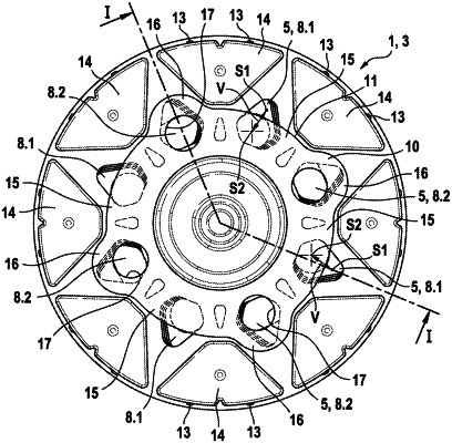
1. A rotor of an electric machine, the rotor comprising a rotor body (3) that is rotatable about a rotor axis (2) and comprising at least one rotor sub-body (4), wherein each of the at least one rotor sub-bodies (4) includes at least one cooling duct (5) having at ends thereof a cooling duct opening (8.1, 8.2), wherein the cooling duct opening (8.1) at a first end of the at least one cooling duct (5) is radially farther outside than the cooling duct opening (8.2) at a second end of the at least one cooling duct (5) such that an airflow is established in the cooling duct (5) by virtue of centrifugal forces in the rotation of the rotor (1), wherein, on one of two end sides of the rotor body (3), a first cover element (10) covers a radially innermost partial cross section of the cooling duct opening (8.1) at the first end of the at least one cooling duct (5),
wherein the first cover element (10) covers the radially innermost partial cross section of the cooling duct opening (8.1) at the first end of the at least one cooling duct (5) with a peripheral portion that, relative to the rotor axis (2), leaves a radially outermost partial cross section of the cooling duct opening (8.1) at the first end of the at least one cooling duct (5) uncovered as a cooling duct exit (8.1);
wherein the cooling duct opening (8.2) at the second end of the at least one cooling duct (5) is a cooling duct entrance, and wherein an inflow, relative to the rotor axis (2), is an axial inflow and is upstream of the cooling duct entrances (8.2); and
wherein a geometric center (S1) of the cooling duct exit (8.1), relative to the rotor axis (2), is radially offset from a geometric center (S2) of the cooling duct entrance (8.2), and
wherein a second cover element (12) is disposed on an opposite end side of the rotor body (3) from the first cover element (10), wherein a cooling duct entrance (8.2) of each of the at least one cooling duct (5), on a radially outermost partial cross section, is covered by one of the first or second cover elements (10, 12), and the cooling duct exit (8.1) of the respective at least one cooling duct (5) is covered by the other of the first or second cover elements (10, 12) on a radially innermost partial cross section such that each at least one cooling duct (5) includes a radial offset (V) between non-covered or open cross sections of the cooling duct openings (8.1, 8.2).
|