| CPC H02K 1/2791 (2022.01) [H02K 1/278 (2013.01); H02K 15/03 (2013.01)] | 10 Claims |

|
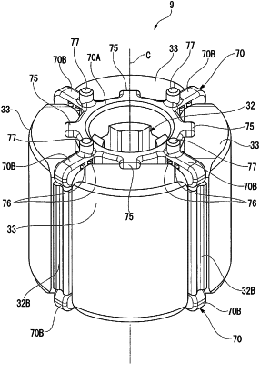
1. A rotor, which rotates by receiving a magnetic field of a stator, comprising:
a rotor core that rotates integrally with a rotary shaft of a motor;
a plurality of permanent magnets arranged on the outer peripheral part of the rotor core;
a substantially tubular magnet cover that covers the exterior of the rotor core and a plurality of the permanent magnets, and has a flange part which is bent radially inward at the end in a direction along a rotation axis; and
a load reception block that is disposed between the flange part and an end surface of the rotor core in the direction along the rotation axis, and abuts against the flange part and the rotor core,
wherein at least the end on one side of the permanent magnet in the direction along the rotation axis protrudes outward from the end of the rotor core on the same side in the direction along the rotation axis,
an abutting part of the load reception block with the flange part is arranged at a position more outside than the end of the permanent magnet in the direction along the rotation axis,
the rotor core has
a substantially cylindrical core main body part, and
a plurality of salient poles protruding in a radial direction from an outer peripheral surface of the core main body part;
the plurality of the permanent magnets are disposed between the plurality of adjacent salient poles and abut against the salient poles; and
the load reception block has:
an annular part that is arranged to overlap an end surface of the core main body part in the direction along the rotation axis, and
a plurality of legs that are arranged to protrude in the radial direction from an outer peripheral surface of the annular part and overlap an end surface of each of the salient poles in the direction along the rotation axis.
|