| CPC H01R 13/639 (2013.01) [H01R 4/16 (2013.01); H01R 4/183 (2013.01); H01R 25/162 (2013.01)] | 6 Claims |

|
1. A joint connector for connecting a plurality of wires, comprising:
the plurality of wires extending in an extending direction;
a plurality of terminals to be respectively connected to front end parts in the extending direction of the plurality of wires;
a lower housing for accommodating the plurality of terminals;
a busbar to be disposed in the lower housing; and
an upper cover to be assembled with the lower housing,
wherein:
the busbar includes a plurality of tabs,
each of the plurality of terminals includes a busbar connecting portion to be connected to each of the plurality of tabs and a wire connecting portion to be connected to each of the plurality of wires,
the plurality of wires drawn out rearward in the extending direction from the lower housing include bent portions folded forward in the extending direction,
the upper cover includes wire pressing portions for holding the plurality of wires folded forward in the extending direction,
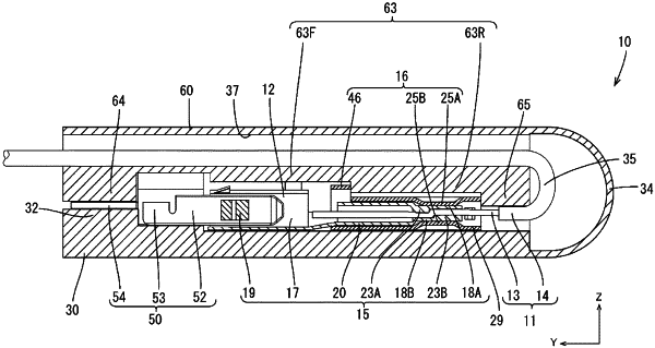
the wire connecting portion includes a sandwiching portion extending along the extending direction, the sandwiching portion sandwiching one of the plurality of wires, and a slide portion disposed outside the sandwiching portion, the slide portion being movable along the extending direction, and the slide portion includes a pressurizing portion for pressurizing the sandwiching portion toward the wire with one of the plurality of wires sandwiched by the sandwiching portion,
the slide portion is a member separate from the sandwiching portion,
the slide portion is slidable between a full locking position and a partial locking position,
the slide portion is so configured that the pressurizing portion presses the sandwiching portion at the full locking position, and
the sandwiching portion is separated from the pressurizing portion at the partial locking position.
|