| CPC H01R 12/515 (2013.01) [H05K 1/119 (2013.01); H01R 4/38 (2013.01); H05K 2201/09163 (2013.01); H05K 2201/10393 (2013.01); H05K 2201/10409 (2013.01)] | 12 Claims |

|
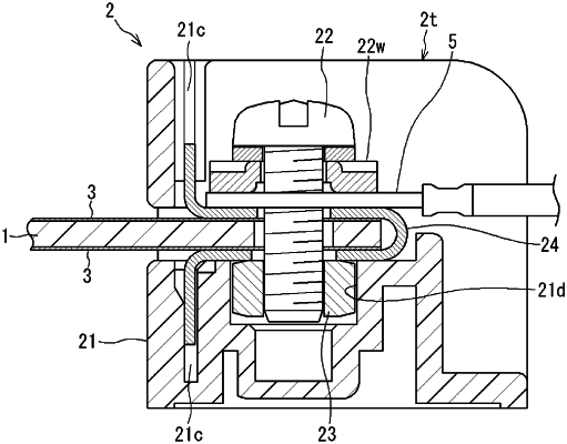
1. A connection structure between a printed circuit board and a terminal block, the connection structure comprising:
an insertion portion at one end of the printed circuit board, wherein a surface of the insertion portion comprises a pattern;
a terminal-block main body comprising a receiving port that receives the insertion portion;
a nut held in the terminal-block main body;
an end portion of an electric wire or a crimp terminal attached to an electric wire; and
a screw that fixes the terminal-block main body to the printed circuit board upon being tightened into the nut, wherein
the pattern and one of the end portion or the crimp terminal are interposed between the screw and the nut when the insertion portion is inserted into the receiving port.
|