| CPC H01L 29/42328 (2013.01) [H01L 29/42336 (2013.01); H01L 29/66825 (2013.01); H01L 29/7883 (2013.01); H10B 41/30 (2023.02); H10B 41/40 (2023.02)] | 15 Claims |

|
1. A semi-floating gate device, wherein the semi-floating gate device comprises:
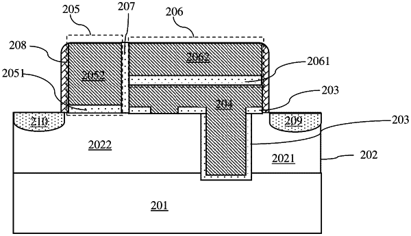
a first conductive type lightly doped source region, a first conductive type lightly doped drain region, and a second conductive type doped first well region formed in a semiconductor substrate;
a floating gate structure covers a selected area of the first well region, and a surface of the first well region covered by the floating gate structure is used to form a conductive channel for electrically connecting the lightly doped source region and the lightly doped drain region;
the floating gate structure comprises a floating gate dielectric layer, a dielectric layer window, and a floating gate material layer;
the floating gate material layer is a second conductive type doped polysilicon layer;
the floating gate structure further covers a surface of the lightly doped drain region, the dielectric layer window is located on the surface of the lightly doped drain region, and the floating gate material layer and the lightly doped drain region contact at the dielectric layer window to form a PN structure;
a first conductive type heavily doped source region is formed in a selected surface area of the lightly doped source region;
a first conductive type heavily doped drain region is formed in a selected surface area of the lightly doped drain region;
on a surface of the semiconductor substrate, the floating gate structure comprises a first side surface and a second side surface;
the first conductive type heavily doped source region is self-aligned with the first side surface of the floating gate structure;
a first control gate is superposed on a top of the floating gate structure, and the first control gate is formed by superposing a first gate dielectric layer and a first gate conductive material layer;
a second control gate is disposed on a surface of the lightly doped drain region between the first conductive type heavily doped drain region and the second side surface of the floating gate structure, and the second control gate is formed by superposing a second gate dielectric layer and a second gate conductive material layer;
the first control gate and the second control gate are isolated by an inter-gate dielectric layer;
the inter-gate dielectric layer is also located between the second control gate and the second side surface of the floating gate structure;
the first control gate is used to control a reading operation of the semi-floating gate device;
the second control gate is used to control an erasing and writing operation of the semi-floating gate device; and
by independently applying different voltages to the first control gate and the second control gate, simultaneous reading and writing can be achieved.
|