| CPC G21C 15/257 (2013.01) [F28D 15/046 (2013.01); F28D 2021/0054 (2013.01)] | 8 Claims |

|
1. A unit cell configured to remove heat generated by a nuclear reactor, the unit cell comprising:
a core block material; and
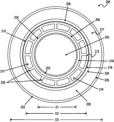
a plurality of devices disposed throughout the core block material, wherein at least one device of the plurality of devices comprises a heat pipe comprising:
a length;
an inner housing comprising an outer surface, wherein the inner housing defines an inner volume configured to accommodate a heat source;
an outer housing comprising an inner surface, wherein the outer housing is configured about the inner housing and the heat source;
a wick positioned between the inner housing and the outer housing and extending along at least a portion of the length of the heat pipe, wherein the wick comprises a capillary material, wherein the wick is configured to contact at least a portion of the outer surface of the inner housing, wherein the wick is configured to contact at least a portion of the inner surface of the outer housing, and wherein the wick defines an intermediate volume between the inner housing and the outer housing; and
a working fluid within the intermediate volume, wherein the working fluid is configured to evaporate at a first end of the heat pipe, wherein the working fluid is further configured to condense at a second end of the heat pipe, wherein the wick is configured to return working fluid that has condensed at the second end of the heat pipe to the first end of the heat pipe, and wherein the evaporation and condensation of the working fluid is configured to transfer heat from the first end of the heat pipe to the second end of the heat pipe for dissipation.
|