| CPC G03G 15/2053 (2013.01) [G03G 15/2039 (2013.01); G03G 15/2042 (2013.01); H05B 3/0095 (2013.01); G03G 2215/2035 (2013.01)] | 7 Claims |

|
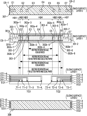
1. A heater for use in an image heating device, the heater comprising:
a substrate;
a first heating block provided on the substrate and configured to generate heat by electric power supplied thereto;
a second heating block provided on the substrate at a position different from the position of the first heating block in a longitudinal direction of the substrate and configured to generate heat by electric power supplied thereto;
a first temperature sensor provided at a position corresponding to the first heating block in the longitudinal direction of the substrate;
a second temperature sensor provided at a position corresponding to the second heating block in the longitudinal direction of the substrate;
a first conductive pattern provided on the substrate, the first conductive pattern is electrically coupled to the first temperature sensor at a first end of the first conductive pattern; and
a second conductive pattern provided on the substrate, the second conductive pattern is electrically coupled to the second temperature sensor at a first end of the second conductive pattern,
wherein a second end of the first conductive pattern and a second end of the second conductive pattern are arranged in a direction perpendicular to the longitudinal direction of the substrate.
|