| CPC G03G 15/162 (2013.01) [G03G 15/1615 (2013.01); G03G 21/1864 (2013.01); G03G 2215/0869 (2013.01)] | 9 Claims |

|
1. A belt unit, comprising:
a belt that is endless;
a plurality of stretching rollers that are arranged in contact with an inner circumferential surface of the belt;
a pair of side frames that rotatably support opposite end parts of the stretching rollers in an axial direction thereof; and
one or more shafts of which opposite end parts in an axial direction thereof are non-rotatably supported by the side frames,
the belt unit being attachable and detachable with respect to a main body of an image forming apparatus,
wherein
the pair of side frames are each provided with bearing holes that rotatably support the opposite end parts of the plurality of stretching rollers and positioning holes into which the opposite end parts of the shafts are inserted;
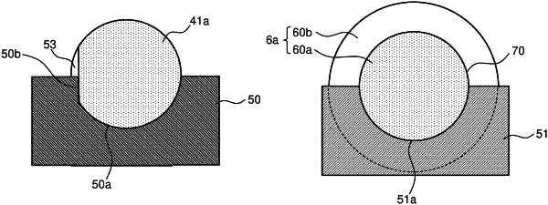
the shafts each have formed therein a first engagement groove that engages with a first holding jig that horizontally holds that shaft during assembly of the belt unit;
the plurality of stretching rollers each have formed therein a second engagement groove that engages with a second holding jig that horizontally holds that stretching roller during assembly of the belt unit;
when the first engagement groove is in engagement with the first holding jig, the shafts are arranged opposite the positioning holes corresponding thereto, and have a phase thereof restricted in a circumferential direction thereof; and
when the second engagement groove is in engagement with the second holding jig, the stretching rollers are arranged opposite the bearing holes corresponding thereto.
|