| CPC F41B 7/006 (2013.01) [F41A 9/35 (2013.01)] | 3 Claims |

|
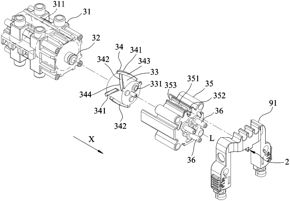
1. A revolving sequential launching device adapted to be used in a toy projectile launcher, the toy projectile launcher being loaded with a plurality of toy projectiles, said revolving sequential launching device comprising:
a guide member adapted to be disposed on the toy projectile launcher; and
a launch unit being movable relative to said guide member along an axis that extends in a front-rear direction, said launch unit including
a front housing that has a gas storage chamber,
a first gas conduit that extends rearwardly from said front housing and that is in fluid communication with said gas storage chamber,
a revolving sleeve that is rotatably sleeved on said first gas conduit, and that has a guide hole being in fluid communication with said first gas conduit,
a cam rail subunit that is disposed on an outer surface of said revolving sleeve,
a rear housing that is mounted on a rear end of said front housing and surrounding said cam rail subunit, and
a plurality of second gas conduits that extend rearwardly from said rear housing and that are adapted to be directed respectively to the projectiles;
wherein said cam rail subunit is movable to be in sliding contact with said guide member during movement of said launch unit along said axis such that further movement of said launch unit along said axis drives rotation of said revolving sleeve;
wherein the rotation of said revolving sleeve brings said guide hole to be sequentially aligned with said second gas conduits, thereby discharging sequentially the toy projectiles by gas from said first gas conduit;
wherein said rear housing has a guide slot that has a rear end region and a front end region opposite to each other in said front-rear direction;
wherein said launch unit is operable between a first operation state and a second operation state;
wherein when said launch unit is in said first operation state, said rear end region is adjacent said guide member, and said launch unit is rearwardly movable to insert said guide member into said guide slot via said rear end region, and is further rearwardly movable toward said second operation state to drive the rotation of said revolving sleeve in a rotational direction by virtue of the sliding contact between said cam rail subunit and said guide member; and
wherein when said launch unit is in said second operation state, said front end region is adjacent to said guide member, and said launch unit is forwardly movable toward said first operation state to drive the rotation of said revolving sleeve in said rotational direction by virtue of the sliding contact between said cam rail subunit and said guide member.
|