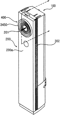
| CPC F24F 1/0018 (2013.01) [F24F 1/0007 (2013.01); F24F 1/0011 (2013.01); F24F 1/0029 (2013.01); F24F 1/005 (2019.02); F24F 13/082 (2013.01); F24F 13/1426 (2013.01); F24F 2013/1446 (2013.01); F24F 2013/146 (2013.01)] | 16 Claims |

|
1. An indoor unit of an air conditioner, comprising:
a case comprising a suction inlet and a discharge outlet to communicate an inner space of the case with an indoor space;
a first guide housing disposed inside the case;
a fan housing assembly movably disposed at the first guide housing and to discharge air in the case through the discharge outlet, the fan housing assembly comprising a fan to flow the air in the case; and
an actuator to move the fan housing assembly;
wherein the actuator moves the fan housing assembly forward or rearward along a central axis, the central axis passing the discharge outlet,
a guide motor disposed at the fan housing assembly to provide a driving force to move the fan housing assembly in a forward and rearward direction;
a guide shaft horizontally disposed at the fan housing assembly, and rotatably assembled to the fan housing assembly to rotate by receiving a rotational force of the guide motor;
a first guide gear coupled to a left side of the guide shaft and rotated with the guide shaft;
a second guide gear coupled to a right side of the guide shaft and rotated with the guide shaft;
a first rack disposed at the first guide housing and engaged with the first guide gear; and
a second rack disposed at the first guide housing and engaged with the second guide gear,
wherein, when the guide motor is operated, the first guide gear is moved along the first rack when the first guide gear is engaged with the first rack and the second guide gear is moved along the second rack when the second guide gear is engaged with the second rack,
wherein the first rack and the second rack are disposed bilaterally symmetrical to each other with respect to the central axis passing a center of the discharge outlet in the forward and rearward direction, when viewed from the front, and
wherein the first guide gear and the second guide gear are disposed bilaterally symmetrical to each other with respect to the central axis passing a center of the discharge outlet in the forward and rearward direction, when viewed from the front.
|