| CPC F16K 31/0675 (2013.01) [F16K 1/44 (2013.01); F16K 17/048 (2013.01); F16K 31/0606 (2013.01); F16K 31/0627 (2013.01); F16K 31/0631 (2013.01); Y10T 137/87877 (2015.04)] | 7 Claims |

|
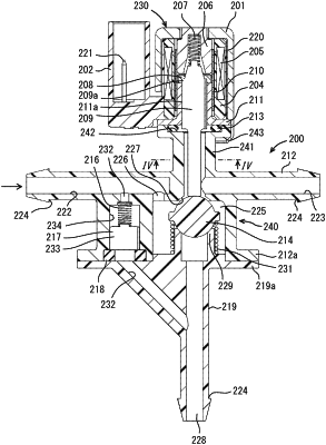
7. A fluid system, comprising:
a tank for working fluid;
a pump which sucks the working fluid from the tank and discharges the working fluid in a high pressure;
a pipe through which the working fluid from the pump flows;
a stop valve which is arranged in the pipe, opens the pipe if the pressure of the working fluid in the pipe is equal to or higher than an open pressure and closes the pipe if the pressure of the working fluid in the pipe is less than the open pressure; and
an electromagnetic valve, wherein
the electromagnetic valve including:
a coil which is magnetized if energized;
a core which is arranged in a magnetic circuit of the coil:
a plunger which is arranged in the magnetic circuit of the coil opposed to the core via a magnetic gap;
a valve member which is movable with the plunger;
a valve body which includes an inflow passage of the working fluid, an outflow passage of the working fluid, a normally close valve seat which is formed between the inflow passage and the outflow passage and contacts the valve member, and a pressure relief passage communicating the inflow passage and the outflow passage by bypassing the normally close valve seat;
a normally close compression spring which urges the valve member toward a side to the normally close valve seat; and
a pressure relief valve which is arranged in the pressure relief
passage in the valve body, closes the pressure relief passage, if a pressure of the working fluid in the outflow passage is lower than, is equal to, and is higher by a pressure difference less than a predetermined relief pressure than a pressure of the working fluid in the inflow passage, and opens the pressure relief passage, if the pressure of the working fluid in the outflow passage is higher by a pressure difference equal to or higher than the relief pressure than a pressure of the working fluid in the inflow passage, and wherein
the electromagnetic valve is arranged in the pipe between the pump and the stop valve, and wherein
the relief pressure of the pressure relief valve is smaller than the open pressure of the stop valve.
|