| CPC F15B 13/0402 (2013.01) [F15B 13/0433 (2013.01); F15B 13/0435 (2013.01); F16K 17/0473 (2013.01); F16K 17/048 (2013.01); E02F 9/2207 (2013.01); F15B 2211/522 (2013.01); F15B 2211/526 (2013.01)] | 13 Claims |

|
1. A hydraulic control assembly comprising:
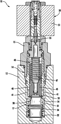
a body, the body defining a valve cavity, a first port, a second port, and a third port, each of the first port, the second port, and the third port being in fluid communication with the valve cavity, the first port being adapted to be fluidly connected to a cylinder of a hydraulic circuit, the second port being adapted to be fluidly connected to a main control valve (MCV) of the hydraulic circuit through which the second port is fluidly connected to a source of hydraulic fluid, and the third port being adapted to be fluidly connected to a tank of the hydraulic circuit;
a hydraulic valve, the hydraulic valve being mounted to the body such that the hydraulic valve is at least partially disposed within the valve cavity, the hydraulic valve comprising an electro-proportional pressure valve and having a nose; and
a check assembly, the check assembly being disposed within the valve cavity and in abutting relationship with the hydraulic valve such that the check assembly is seated against the nose of the hydraulic valve;
wherein the check assembly is configured to permit a flow of hydraulic fluid from the second port to the first port through the check assembly and to prevent the flow of hydraulic fluid from the first port to the second port through the check assembly; and
wherein the hydraulic valve is configured to permit the flow of hydraulic fluid from the first port to the second port through the hydraulic valve once a load pressure at the first port exceeds a threshold pressure and to block the flow of hydraulic fluid from the first port to the second port when the load pressure is below the threshold pressure;
wherein the hydraulic valve includes:
a cage defining a plurality of cross holes and an axial bore,
a movable member disposed within the axial bore of the cage and axially movable over a range of travel with respect to the cage between a closed position in which the movable member occludes the cross holes to fluidly isolate the first port and the second port from each other and an open position in which the first port and the second port are in fluid communication with each other through the cage,
a spring arranged with the movable member to generate a spring force against the movable member to bias the movable member to the closed position such that the flow of hydraulic fluid from the first port to the second port is blocked until the load pressure at the first port is sufficient to overcome the spring force to move the movable member to the open position,
a valve body connected to the cage and defining an internal cavity that is fluidly connectable with the bore of the cage,
a pilot-operated valve disposed intermediately with respect to the cage and the valve body to fluidly isolate the internal cavity of the valve body from the bore of the cage, the pilot-operated valve being subjected to a hydraulic opening force of pilot fluid that is present in the bore of the cage, and
a pilot spring disposed within the internal cavity of the valve body and arranged to subject the pilot-operated valve to a closing spring force;
wherein the pilot-operated valve of the hydraulic valve includes:
a housing fixed within the cavity of the valve body, the housing including a longitudinal passageway having an interior opening and an external opening, the longitudinal passageway being in communication with a transverse pilot passageway and a longitudinal bore, and the housing including a pilot seat circumscribing the interior opening of the longitudinal passageway, and
a pilot poppet moveably disposed within the longitudinal bore of the housing, the pilot poppet adapted to sealingly engage the pilot seat.
|