| CPC F15B 11/15 (2013.01) [F15B 13/021 (2013.01); F15B 15/1476 (2013.01); F15B 15/149 (2013.01); B25F 5/005 (2013.01); F15B 2211/423 (2013.01); F15B 2211/428 (2013.01); F15B 2211/505 (2013.01)] | 14 Claims |

|
1. An automatic oil return structure comprising:
an oil storage container;
a housing spaced apart from the oil storage container and having
an oil storage chamber;
a main body assembly mounted between the oil storage container and the housing and having
a first main channel connected to the oil storage container;
a second main channel connected to the oil storage container and the oil storage chamber of the housing;
a first main channel blocking unit mounted in the first main channel and selectively blocking the first main channel;
a second main channel blocking unit mounted in the second main channel and selectively blocking the second main channel;
an automatic oil reflow channel connected to the oil storage container;
a piston oil channel connected to the oil storage chamber of the housing;
a connecting channel connected to the first main channel;
a main controlling channel connected to the automatic oil reflow channel, the connecting channel and the piston oil channel;
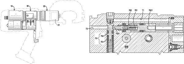
a main controlling unit mounted in the main controlling channel and having
a main blocking unit; and
a main elastic unit configured to push the main blocking unit to block the connecting channel and to connect the piston oil channel and the automatic oil reflow channel; wherein when a pressure in the connecting channel is higher than a set value, the main blocking unit is pushed away and pushed to block the automatic oil reflow channel and to connect the piston oil channel and the connecting channel;
a first pressure regulating channel connected to the connecting channel;
a first controlling channel connected to the first pressure regulating channel;
a second pressure regulating channel connected to the first controlling channel and the oil storage container;
a second controlling channel connected to the first controlling channel;
a pressure regulating controlling unit mounted in the first controlling channel and having
a pressure regulating blocking unit; and
a pressure regulating elastic unit pushing the pressure regulating blocking unit to block the first pressure regulating channel; wherein when a pressure in the first pressure regulating channel is higher than a set value, the pressure regulating blocking unit is pushed away to connect the first pressure regulating channel and the first controlling channel;
an engaging groove formed radially inward on the pressure regulating blocking unit;
an engagement controlling unit mounted in the second controlling channel and having
an engaging unit dividing the second controlling channel into a disengaging segment and a resetting segment which are unconnected with each other; the disengaging segment connected to the first controlling channel; and
an engaging elastic unit configured to push the engaging unit toward the pressure regulating blocking unit; wherein when the pressure in the first pressure regulating channel is higher than the set value and the pressure regulating blocking unit is pushed away to a set distance, the engaging unit is pushed to engage with the engaging groove of the pressure regulating blocking unit such that the pressure regulating blocking unit is unmovable to avoid blocking the first pressure regulating channel; and
a disengaging channel connected to the disengaging segment of the second controlling channel and the first main channel.
|