| CPC F01M 11/08 (2013.01) [B01D 45/14 (2013.01); B04B 7/18 (2013.01); B33Y 80/00 (2014.12)] | 11 Claims |

|
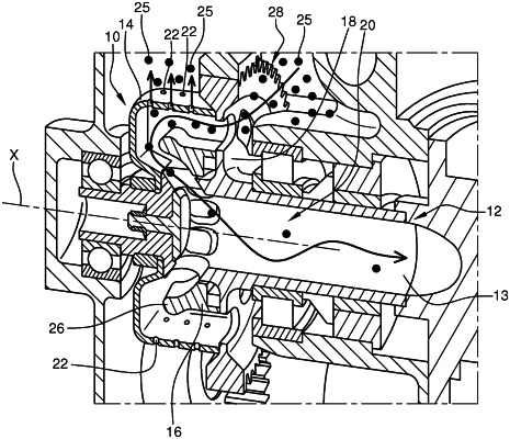
1. A centrifugal degasser of an air/oil mixture of a turbomachine, comprising:
a hollow shaft extending along an axis X and defining an internal air circulation cavity;
a pinion configured for rotating the hollow shaft; and
an annular chamber configured for centrifugal separation of said air/oil mixture, the annular chamber being arranged around the hollow shaft and forming a fluid passage vein, the fluid passage vein comprising an inlet oriented axially for feeding the annular chamber with said air/oil mixture, and a first outlet oriented radially inwards for the exit of a de-oiled air portion separated from said air/oil mixture, the first outlet being in fluid communication with said internal air circulation cavity for discharging the de-oiled air portion to an outside of the centrifugal degasser, the annular chamber further comprising a second oil outlet oriented radially outwards and configured for discharging an oil portion separated from said air/oil mixture to the outside of the centrifugal degasser,
wherein the annular chamber and the pinion form a single piece.
|