| CPC E04B 1/043 (2013.01) | 9 Claims |

|
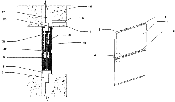
1. A fabricated concrete connection structure, comprising shear wall members (1), tops of the shear wall members (1) being fixedly connected to a plurality of connection female heads (2), and the plurality of connection female heads (2) being arranged at equal intervals along length directions of the shear wall members (1); a plurality of reinforcing cage pre-formed holes (4) being disposed on the shear wall members (1), the plurality of reinforcing cage pre-formed holes (4) being disposed at equal intervals along the length directions of the shear wall members (1), the plurality of reinforcing cage pre-formed holes (4) and the plurality of connection female heads (2) being arranged at intervals, and the reinforcing cage pre-formed holes (4) penetrating through the tops and bottoms of the shear wall members (1); a plurality of connection male heads (3) being arranged at the bottoms of the shear wall members (1), the plurality of connection male heads (3) being arranged at equal intervals along the length directions of the shear wall members (1), and the plurality of connection male heads (3) being in one-to-one correspondence with the plurality of connection female heads (2); and one side of the bottom of each of the shear wall members (1) being fixedly connected to a folding plate (5); wherein
each of the connection female heads (2) comprises a female head connection seat (6), and the female head connection seat (6) is fixedly connected to the top of the shear wall member (1); and one side of the female head connection seat (6) is fixedly connected to a first reinforcing steel joint (11), the other side of the female head connection seat (6) is fixedly connected to a first sleeve pipe (7), a fastening part is sleeved on an outer side of the first sleeve pipe (7), and an inner wall of the fastening part is slidably connected to an outer wall of the first sleeve pipe (7);
a second sleeve pipe (10) is sleeved inside the first sleeve pipe (7), and an outer wall of the second sleeve pipe (10) is fixedly connected to an inner wall of the first sleeve pipe (7); a plurality of open grooves are disposed at one end of the second sleeve pipe (10), the plurality of open grooves are disposed at equal intervals along a circumference of the second sleeve pipe (10), a plurality of clamp beads (13) are connected inside the open grooves in a clamping mode, and the plurality of clamp beads (13) are connected to the fastening part in a clamping mode; and the outer wall of the second sleeve pipe (10) is slidably connected to the inner wall of the fastening part;
an inner wall of the second sleeve pipe (10) is slidably connected to a first sliding part, an inner wall of the first sliding part is slidably connected to a fourth sleeve pipe (21), and one end of the fourth sleeve pipe (21) is fixedly connected to a side wall of the female head connection seat (6);
an inner wall of the fourth sleeve pipe (21) is fixedly connected to a third sleeve pipe (20), an inner wall of the third sleeve pipe (20) is slidably connected to a second sliding part, a connection rod (19) is arranged in a center of the second sliding part, one end of the connection rod (19) is fixedly connected to a center of the side wall of the female head connection seat (6), the other end of the connection rod (19) is fixedly connected to a first push block (18), a side wall of the first push block (18) abuts against the second sliding part, and a top of one end of the second sliding part is slidably connected to the inner wall of the first sliding part; and
a first sealing ring (24) is arranged on the inner wall of the third sleeve pipe (20), and the first sealing ring (24) is arranged in contact with a side wall of the second sliding part.
|