| CPC C02F 1/26 (2013.01) [C02F 1/46109 (2013.01); C02F 1/66 (2013.01); C25C 1/08 (2013.01); C25C 7/02 (2013.01); C02F 2001/46133 (2013.01); C02F 2101/20 (2013.01); C02F 2103/16 (2013.01); C02F 2201/005 (2013.01); C02F 2201/46135 (2013.01); C02F 2201/4614 (2013.01); C02F 2201/46145 (2013.01); C02F 2201/4615 (2013.01); C02F 2209/06 (2013.01)] | 10 Claims |

|
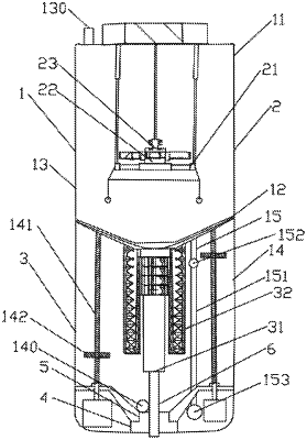
1. A device for efficiently recycling nickel from wastewater, comprising a housing (1), and an extraction unit (2) and an electro-deposition unit (3) which are respectively arranged inside the housing (1), wherein
the housing (1) comprises a housing body (11), and a baffle plate (12) which is arranged inside the housing body (11) and divides the housing body (11) into an extraction cavity (13) and an electro-deposition cavity (14) from top to bottom; liquid mixing equipment connected to an external nickel-containing wastewater tank and a composite extraction agent is arranged at an upper end of the housing body (11); the baffle plate (12) comprises a funnel-shaped baffle plate body, and a connection pipe which is arranged at a lower end of the baffle plate body and is used for connecting the extraction cavity (13) with the electro-deposition cavity (14); a first discharge outlet (130) is formed in a top of the extraction cavity (13); a second discharge outlet (140) is formed in a bottom of the electro-deposition cavity (14); the first discharge outlet (130), the second discharge outlet (140) and the connection pipe are all provided with electromagnetic valves; the electro-deposition cavity (14) is provided with liquid adding equipment and a liquid measurement component (15);
the liquid measurement component (15) comprises a sensing connection rod (151), a floating ball (152) movably arranged on the sensing connection rod (151), a signal converter (153) arranged at one end of the sensing connection rod (151) and located at the bottom of the electro-deposition cavity (14), and a display instrument connected to the signal converter (153);
the extraction unit (2) comprises an oscillating and floating component (21) arranged in the extraction cavity (13), a rotating component (22) arranged at an oscillating and floating end of the oscillating and floating component (21), and a liquid inlet component (23) arranged above the rotating component (22);
the oscillating and floating component (21) comprises an expansible and contractible module (211) mounted in the extraction cavity (13), and a mounting seat (212) arranged at an expansible and contractible end of the expansible and contractible module (211) and used for mounting the rotating component (22);
the mounting seat (212) comprises a mounting seat body (2121), a V-shaped cutting assembly (2122) with one end arranged on the mounting seat body (2121), an oscillating and floating ring (2123) connected to the other end of the V-shaped cutting assembly (2122), a floating ring (2124) connected to the oscillating and floating ring (2123) through a steel rope, and an oscillating and floating ball assembly (2125) hung on the floating ring (2124) through a steel rope;
the liquid inlet component (23) comprises a temporary liquid storage cavity (231) arranged on the rotating component (22), and a liquid spraying component (232) arranged on the temporary liquid storage cavity (231); the liquid spraying component (232) comprises a communication pipe (2321), of which, one end is mounted on the temporary liquid storage cavity (231) and an upper surface is provided with a liquid leaking hole, and an end pipe (2322) arranged at the other end of the communication pipe (2321) and provided with a liquid leaking hole in a side surface; the temporary liquid storage cavity (231) is connected with the liquid mixing equipment; and
the electro-deposition unit (3) comprises a cathode assembly (31) arranged inside the electro-deposition cavity (14) through a first mounting unit, and an anode assembly (32) mounted inside the electro-deposition cavity (14) through a second mounting unit and located on an outer side of the cathode assembly (31).
|