| CPC B65G 21/14 (2013.01) | 10 Claims |

|
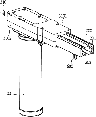
1. An electric guide rail type conveying system, comprising:
a driving motor;
a guide rail, a passage which penetrates through the guide rail in a lengthwise direction being disposed in the guide rail, and an opening communicated with the passage being formed in one side of the guide rail in the lengthwise direction;
a main transmission case and an auxiliary transmission case correspondingly disposed at two ends of the guide rail, the driving motor being disposed on the main transmission case;
a conveying member disposed on a structure formed by the main transmission case, the guide rail and the auxiliary transmission case; and
a moving trolley disposed on the conveying member, moving on the guide rail, and used for carrying external goods;
wherein, the auxiliary transmission case comprises:
an auxiliary transmission case body; and
a guide wheel disposed on the auxiliary transmission case body, one portion of the conveying member being movably disposed on the guide wheel during use, and a moving direction of the conveying member being changed by the guide wheel;
wherein, the main transmission case comprises:
a main transmission case body;
a first rotating member rotatably disposed on the main transmission case body, one end of the conveying member being elastically deformably wound on the first rotating member in a first winding direction;
a second rotating member rotatably disposed on the main transmission case body and spaced apart from the first rotating member, an axial direction of the second rotating member being basically parallel with an axial direction of the first rotating member, the other end of the conveying member being elastically deformably wound on the second rotating member in a second winding direction opposite to the first winding direction; and
a balance rotating member rotatably disposed on the main transmission case body and rotatably connected to the first rotating member and the second rotating member, such that when one of the first rotating member and the second rotating member rotates, the other one of the first rotating member and the second rotating member is driven to rotate in a same rotation direction through the balance rotating member;
wherein, before installation, the conveying member is basically wound on the first rotating member and the second rotating member;
wherein, when a relative outer portion of the conveying member wound on the first rotating member is separated from the first rotating member, a first elastic resilience opposite to the first winding direction is generated; with the increase of a portion, separated from the first rotating member, of the conveying member, the first elastic resilience will increase; otherwise, the first elastic resilience will decrease;
wherein, when a relative outer portion of the conveying member wound on the second rotating member is separated from the second rotating member, a second elastic resilience opposite to the second winding direction is generated; with the increase of a portion, separated from the second rotating member, of the conveying member, the second elastic resilience will increase; otherwise, the second elastic resilience will decrease;
wherein, when the driving motor drives the first rotating member to rotate, a portion, not wound on the first rotating member, of the conveying member will be wound on the first rotating member in the first winding direction, a portion, wound on the first rotating member, of the conveying member will be driven by the first rotating member to be tensioned, the relative outer portion, wound on the second rotating member, of the conveying member will be driven by the balance rotating member to be separated from the second rotating member in a direction opposite to the second winding direction, and a portion, wound on the second rotating member, of the conveying member will be driven by the second rotating member to be loosened, such that the second elastic resilience is opposite to the first elastic resilience in direction and is basically identical with the first elastic resilience in magnitude;
wherein, when the driving motor drives the second rotating member to rotate, a portion, not wound on the second rotating member, of the conveying member will be wound on the second rotating member in the second winding direction, a portion, wound on the second rotating member, of the conveying member will be driven by the second rotating member to be tensioned, the relative outer portion, wound on the first rotating member, of the conveying member will be driven by the balance rotating member to be separated from the first rotating member in a direction opposite to the first winding direction, and a portion, wound on the first rotating member, of the conveying member will be driven by the first rotating member to be loosened, such that the first elastic resilience is opposite to the second elastic resilience in direction and is basically identical with the second elastic resilience in magnitude.
|