| CPC B65D 19/0095 (2013.01) [B65D 2519/00273 (2013.01); B65D 2519/00293 (2013.01); B65D 2519/00323 (2013.01); B65D 2519/00333 (2013.01); B65D 2519/00567 (2013.01); B65D 2519/00572 (2013.01)] | 17 Claims |

|
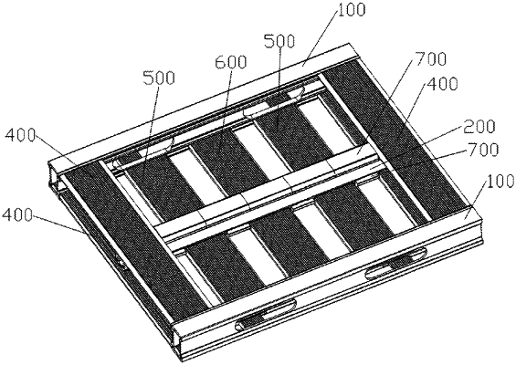
1. An assembled unit having a locking mechanism, the assembled unit comprising:
a pair of lateral guide rails, each of the lateral guide rails being configured with a sliding groove along a direction of extension thereof, with openings of the respective sliding grooves of the pair of the lateral guide rails facing each other;
a pair of first plate members disposed between the pair of the lateral guide rails, wherein
both ends of each of the first plate members are inserted into the sliding groove of a corresponding one of the lateral guide rails,
both ends of each of the lateral guide rails are respectively configured with an engaging structure, which has an engaging position and a disengaging position, and
both ends of each of the first plate members are configured with a corresponding engaging portion,
such that when the engaging portion is slid into the engaging position, the corresponding one of the first plate members is lockedly engaged with the corresponding one of the lateral guide rails, and
when the engaging portion is slid into the disengaging position, the corresponding one of the first plate members are disengageable from the sliding groove of the corresponding one of the lateral guide rails;
a spine member configured with a raised sliding block along its direction of extension, wherein
on a surface of each of the first plate members, a first engaging slot extends in a direction parallel to the lateral guide rails, the first engaging slot opening at a side of each of the first plate members and terminating at a termination position after it extends across part of a surface of the corresponding plate member, with openings of the first engaging slots of the pair of first plate members facing each other;
the sliding block of the spine member is slidable out the opening of the first engaging slot, and an edge of the sliding block can slidably fit with the first engaging slot, such that the spine member is slidable along the first engaging slot but is locked in a direction perpendicular to the surface of the corresponding plate member; and
an end of the spine member is configured with a detachment portion having a predetermined length, such that the spine member can be embedded into or detached from the first engaging slot at the detachment portion in a direction perpendicular to the surface of the corresponding plate member; and
at least one eccentric rotation member, wherein
a raised rotary sliding block is configured at the bottom of the eccentric rotation member;
the rotary sliding block is slidable out the opening of the first engaging slot and stay at the termination position of the first engaging slot, and
an edge of the rotary sliding block rotarily fits with the first engaging slot such that the eccentric rotation member is rotatable about a center of the rotary sliding bock but is locked in a direction perpendicular to the surface of the corresponding one of the first plate members; and
with the rotary sliding block as a starting point, the eccentric rotation member has two arms extending in different directions, with a long arm having a length greater than that of a short arm;
wherein when the assembled unit is to be shifted to an unlocked state, the pair of first plate members are in the engaging positions, the end of the spine member without the detachment portion is slid into the first engaging slot having the eccentric rotation member disposed therein and abuts against the short arm of the eccentric rotation member, and the other end of the spine member configured with the detachment portion overlaps the other first engaging slot, with a length of overlapping not greater than that of the detachment portion such that the spine member at the overlapping position can be directly embedded into the other first engaging slot; and
when the assembled unit is to be shifted from an unlocked state into a locked state, the spine member is slid toward the end thereof configured with the detachment portion until it abuts against the termination position of the first engaging slot accommodating the detachment portion, a length of the detachment portion is smaller than that of the first engaging slot accommodating it such that at least part of a length of the first engaging slot accommodating the detachment portion still fits with the gliding block of the spine member, and the eccentric rotation member is rotated such that its long arm abuts against the end of the spine member without the detachment portion.
|