| CPC B60L 53/22 (2019.02) [B60L 50/51 (2019.02); B60L 50/60 (2019.02); B60L 53/24 (2019.02); B60L 55/00 (2019.02); H02M 1/14 (2013.01); H02M 5/4585 (2013.01); H02M 7/53871 (2013.01); H02P 27/08 (2013.01); B60L 53/18 (2019.02); B60L 2210/30 (2013.01); B60L 2210/40 (2013.01); B60L 2210/42 (2013.01); B60L 2220/12 (2013.01); B60L 2220/54 (2013.01); H02J 2310/48 (2020.01)] | 20 Claims |

|
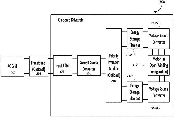
1. A circuit for integrated three-phase AC charging on an electric vehicle or a hybrid-electric vehicle coupled to an AC grid, the circuit comprising:
a dual inverter drive system including an upper charging stage including a first energy storage and a first voltage source converter (VSC1), a lower charging stage including a second energy storage and a second voltage source converter (VSC2), coupled to a motor coupled between the first voltage source converter and the second voltage source converter, the motor having three or more motor windings each coupled to a corresponding AC terminal of each of the VSC1 and the VSC2;
a current source converter (CSC) having a set of CSC AC connections for coupling to the AC grid, a set of CSC DC connections, and a plurality of controllable CSC switches which are operable to control an energy flow between the AC grid and the dual inverter drive system through the CSC;
wherein a leakage inductance of the motor is used to provide an inductance for operating the CSC, and
wherein a back-emf (Vd) is provided by differentially connecting connections of the dual inverter drive system to the set of CSC DC connections to allow for operation of the circuit in a plurality of operation modes during charging through adjustment of the back-emf Vd by controlling the switches of the VSC1 and VSC2.
|