| CPC B43L 9/08 (2013.01) | 6 Claims |

|
1. An equal divider, comprising:
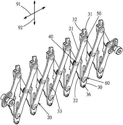
a mainframe, the mainframe is mainly made up of a plurality of first connecting rods and second connecting rods, arranged sequentially one behind the other and pivoted by a plurality of pivoting structures to form a scissor structure, both the first connecting rods and the second connecting rods are long plate, the top side of the mainframe is formed with a plurality of first pivoting parts, the bottom side of the mainframe is formed with a plurality of second pivoting parts, a virtual first axial direction is defined, the two ends of the first axial direction respectively point to the left side and right side of the mainframe, the first pivoting parts are distributed at equal intervals along the first axial direction, the second pivoting parts are distributed at equal intervals along the first axial direction, a virtual second axial direction is defined to be perpendicular to the first axial direction, the two ends of the second axial direction respectively point to the top side and bottom side of the mainframe, each of the first pivoting parts and each of the second pivoting parts match each other along the second axial direction one by one, the top sides of the first connecting rod and the second connecting rod are arranged one behind the other, the first pivoting parts along the thickness direction of the first connecting rods and the second connecting rods pivot the first connecting rods and the second connecting rods, the bottom sides of the first connecting rods and the second connecting rods are arranged one behind the other, the second pivoting parts along the thickness direction of the first connecting rods and the second connecting rods pivot the first connecting rods and the second connecting rods; and
a plurality of indicator plates made of long plates, each indicator plate being configured between the first connecting rod and the second connecting rod, the first pivoting parts and the second pivoting parts configured along the second axial direction respective rivet the same indicator plate, the top side of the indicator plate close to the first pivoting part is configured with an upward protruding indicating part, one side of the indicating part is formed with an indicating face along the second axial direction, the indicating face provides lateral support for the marking tool to draw equidistant marking lines, the mainframe expands or shrinks along the first axial direction, each of the indicating part can be displaced along the first axial direction while maintaining equal distances;
wherein the indicator plate is configured with a long through groove along the second axial direction, the second pivoting part goes through the through groove, each indicating part and each first pivoting part maintain a fixed distance along the second axial direction;
the first pivoting part comprises a first shaft tube and a first screw bolt, the first connecting rod is configured with a first through hole, the indicator plate is configured with a perforation, one end of the first shaft tube is connected to the second connecting rods, the first shaft tube goes through the perforation and the first through hole in the axial direction, the first screw bolt screws into the first shaft tube, the first screw bolt has a first bolt head abutting the first shaft tube, the first bolt head and the first connecting rod are formed with relative stoppers along the axial direction of the first shaft tube, a first gap is formed between the first bolt head and the first connecting rod;
the second pivoting part comprises a second shaft tube and a second screw bolt, the first connecting rods is configured with a second through hole, one end of the second shaft tube is connected to the second connecting rods, the second shaft tube goes through the through groove and the second through hole along the axial direction, the second screw bolt screws into the second shaft tube, the second screw bolt has a second bolt head abutting the second shaft tube, the second bolt head and the first connecting rod are formed with relative stoppers along the axial direction of the second shaft tube, a second gap is formed between the second bolt head and the first connecting rod;
each pivoting structure comprises a third shaft tube and a third screw bolt, each first connecting rod is configured with a third through hole, one end of the third shaft tube is connected to the second connecting rod, the third shaft tube goes through the third through hole in the axial direction, the third screw bolt screws into the third shaft tube, the third screw bolt has a third bolt head abutting the third shaft tube, the third bolt head and the first connecting rod are formed with relative stoppers along the axial direction of the third shaft tube, a third gap is formed between the third bolt head and the first connecting rods;
the radial periphery of the third shaft tube is formed with a supporting face, the first connecting rod abuts the supporting face in the direction facing the second connecting rods.
|