| CPC B28B 1/001 (2013.01) [B28B 17/0081 (2013.01); B33Y 10/00 (2014.12); B33Y 50/02 (2014.12)] | 3 Claims |

|
1. A 3D printing method for a 3D underground complex engineering geological model, comprising:
preparing materials of the geological model comprising:
Step 1: collecting samples of an intact rock mass and a rock mass structure on an engineering site according to an engineering background, and performing indoor tests to obtain component information, physical parameters and mechanical parameters of the intact rock mass and the rock mass structure respectively;
Step 2: determining an aggregate composition and a particle size range of the materials for preparing the intact rock mass and the rock mass structure according to the obtained component information of the intact rock mass and the rock mass structure;
Step 3: determining a geometric similarity ratio, a physical similarity ratio and a mechanical similarity ratio between an engineering prototype and an indoor model based on a similarity theory, thereby calculating the physical and mechanical parameters of the materials of the intact rock mass and the rock mass structure, and selecting a composition of a cementing agent;
Step 4: achieving a control over a printing performance of the materials of the rock mass and the rock mass structure by adding additives, so that the materials of the rock mass and the rock mass structure have a reasonable initial setting time, a flow performance and a self-holding capacity;
Step 5: performing a small-scale 3D printing test at different material ratios and 3D printing parameters according to a uniform design or orthogonal design test method, performing test on physical and mechanical properties for printed material geologic model samples, and judging whether the printed material geologic model samples meet preset physical and mechanical parameter indexes or not; if yes, performing Step 6; or else, resetting the material ratios and the 3D printing parameters, and performing the small-scale 3D printing test, till the printed material geologic model samples meet the preset physical and mechanical parameter indexes; and
Step 6: determining the 3D printing material ratios and the 3D printing parameters of the intact rock mass and the rock mass structure meeting the preset physical and mechanical parameter indexes;
3D printing the geological model comprising:
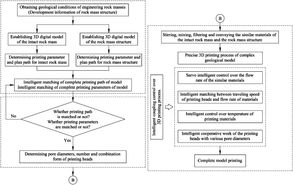
Step S1: establishing a 3D digital model of the intact rock mass and the rock mass structure according to geological conditions of engineering rock masses respectively;
Step S2: determining the printing parameters of the intact rock mass and the rock mass structure respectively, and planning printing paths respectively;
Step S3: planning and generating complete printing paths of the 3D digital model of the intact rock mass and the rock mass structure to achieve a matching between the printing path of the intact rock mass and the printing path of the rock mass structure, and automatically reserving embedding positions of multi-information monitoring sensors;
Step S4: determining pore diameters, number and combination form of print heads according to information of the generated printing path and structural complexity and accuracy requirements of the 3D digital model of the intact rock mass and the rock mass structure; and
Step S5: stirring, mixing and filtering the materials of the intact rock mass and the rock mass structure in an independent stock bin, and conveying the materials to the print heads through a pumping device; under the control of a 3D printing coupling control system, running each of the print heads according to the planned and generated printing paths based on Step 3 to complete printing; wherein the 3D printing coupling control system controls the print heads for 3D printing to achieve a servo control over a flow rate of the materials, an matching between a traveling speed of the print heads and the flow rate of the materials, and a temperature self-adaptive adjustment of a feeding system, and controls a cooperative work of the print heads to complete 3D printing of the geological model; and
testing the 3D printed geological model to determine a model printing effect comprising:
(1) locating periphery boundaries of each printing layer, the rock mass structure and positions of sensors through a laser in the 3D printed geological model, and achieving real-time monitoring of the boundaries of the printing layers, the rock mass structure and the positions of the sensors in the 3D printed geological model;
(2) after the 3D printing of the geological model, arranging a plurality of vertical micro boreholes in a vertical direction and a plurality of transverse micro boreholes in a transverse direction of the 3D printed geological model, and performing endoscopy by using an endoscope to test the printing effect of the structure at a designated position, so that the test of spatial positions of interior structures of the 3D printed geological model is completed; and
(3) after the 3D printing of the geological model, taking rock mass and rock mass structure samples in different positions of the 3D printed geological model in different directions, and performing tests on physical and mechanical properties to test whether relevant properties reach preset parameter indexes or not.
|