| CPC B05C 5/0254 (2013.01) [B05C 5/0262 (2013.01); B05C 13/02 (2013.01); H01M 4/0404 (2013.01)] | 5 Claims |

|
1. A coating shim for electrode slurry discharge, comprising:
an open side in a discharge direction of the electrode slurry based on a cross-sectional structure of the coating shim;
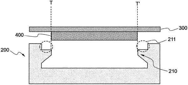
a guide portion formed at opposite sides of the coating shim and having a structure protruding in a width direction of the open side of the coating shim so as to decrease a width of an electrode slurry discharge flow path,
wherein the guide portion has a shape in which a height protruding in the width direction of the discharge flow path increases continuously along the discharge direction from an upstream edge of the guide portion to reach a maximum height;
a step portion formed vertically to an end of the electrode slurry discharge flow path so as to increase the width of the discharge flow path; and
a horizontal portion connecting a downstream edge of the guide portion and the vertically formed step portion,
wherein the step portion is formed at opposite sides in the width direction of the electrode slurry discharge flow path,
wherein the width of the discharge flow path formed by the step portion at the end of the discharge flow path is in a range of 0.5 to 10% greater than a beginning width direction length of the discharge flow path.
|