| CPC B01D 5/0051 (2013.01) [B01D 5/009 (2013.01); B01D 53/002 (2013.01); F01M 13/04 (2013.01); B01D 2258/01 (2013.01); F01M 2013/0411 (2013.01)] | 17 Claims |

|
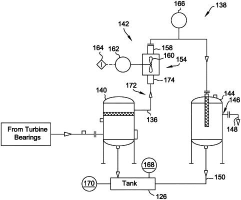
1. A vapor separation system comprising:
a cooler comprising an inlet oriented to receive an air-oil-water vapor mixture, and an outlet oriented to discharge the oil and water in different phases of matter from the cooler;
a separation tank downstream from the cooler for receiving the air-oil-water mixture and condensed liquids discharged from the cooler, wherein the separator tank comprises a vent for discharging vaporized water and air separated from the liquefied oil;
a first sensor at the outlet of the cooler; and
a controller communicatively coupled to the cooler, wherein the controller is configured to:
receive temperature feedback from the first sensor; and
cool, using the cooler and based on the temperature feedback, the air-oil-water mixture to a separation temperature that liquifies at least a portion of the oil in the air-oil-water mixture while maintaining at least a portion of the water in the air-oil-water mixture in a vaporized state.
|