| CPC A61M 39/10 (2013.01) [F16L 37/46 (2013.01); F16L 2201/44 (2013.01)] | 16 Claims |

|
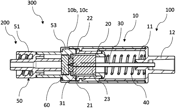
1. A coupling system for a closed fluid transfer system, the coupling system comprising:
A) a coupling member comprising:
a coupling member housing comprising a fluid connection and a coupling side, wherein the coupling member housing provides a longitudinal axis extending from the fluid connection toward the coupling side;
a spike with at least one fluid opening, which is held in a spike receptacle of the housing arranged at the fluid connection and extends into the coupling member housing in the direction of the longitudinal axis, wherein the at least one fluid opening is arranged in an end portion of the spike facing the coupling side;
a sealing member receptacle arranged in the coupling member housing on the coupling side; and
a sealing member arranged in the sealing member receptacle,
wherein the coupling member housing comprises a housing portion, which at least partially surrounds the sealing member receptacle in an axial direction with respect to the longitudinal axis and comprises a coupling member housing threaded portion on the inner surface facing the sealing member;
wherein the sealing member receptacle with the sealing member is moveable in the direction of the longitudinal axis between a sealing member receptacle position with maximum distance to the fluid connection and a sealing member receptacle position with minimum distance to the fluid connection, and
wherein the coupling member housing threaded portion is configured such that a sealing member receptacle guiding structure of the sealing member receptacle is movable in engagement with the coupling member housing threaded portion between the sealing member receptacle position with maximum distance to the fluid connection and the sealing member receptacle position with minimum distance to the fluid connection, wherein the coupling member housing threaded portion provides a height/length of the thread in the direction of the longitudinal axis between the sealing member receptacle position with maximum distance to the fluid connection and the sealing member receptacle position with minimum distance to the fluid connection, which is more than the height/length of the sealing member receptacle guiding structure in this direction; and
B) a mating coupling member for coupling with the coupling member, the mating coupling member comprising:
a mating coupling member housing comprising a mating coupling member fluid connection and a mating coupling side, wherein the mating coupling member housing comprises a mating coupling member longitudinal axis extending from the mating coupling member fluid connection toward the mating coupling side, and
a mating coupling member sealing member, which is arranged in the mating coupling member housing and forms at least a part of a mating coupling side front surface of the mating coupling element together with the mating coupling member housing,
wherein the mating coupling member housing comprises a mating coupling member guiding structure, which is configured such that the mating coupling member is movably guided in the direction of the longitudinal axis relative to the coupling member by the coupling member housing threaded portion of the coupling member,
wherein the coupling system is configured such that the fluid opening of the coupling member in a state connected to the mating coupling member, in which the sealing member receptacle is located in the position with minimum distance to the fluid connection of the coupling member, is at least partially arranged on a side of the mating coupling member sealing member of the mating coupling member facing toward the mating coupling member fluid connection, and
wherein the coupling member housing threaded portion of the coupling member is configured such that the mating coupling member guiding structure and the sealing member receptacle structure are jointly movable guided by the coupling member housing threaded portion.
|