| CPC A61F 2/4455 (2013.01) [A61F 2/447 (2013.01); A61F 2002/30784 (2013.01); A61F 2002/3081 (2013.01); A61F 2002/30841 (2013.01); A61F 2002/30985 (2013.01); A61F 2310/00023 (2013.01)] | 20 Claims |

|
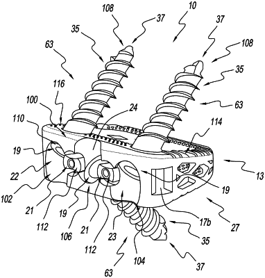
1. An implant for a surgical procedure, the implant comprising:
a plurality of anchoring members each having a shaft, a head on one end of the shaft, and a tip on another end of the shaft;
a cage having a front, a rear, a central cavity, an upper surface, a lower surface, a first angled bore in a first lateral side of the front that extends into the central cavity, a second angled bore in a second lateral side of the front that extends into the central cavity, and a third angled bore in the front between the first angled bore and the second angled bore that extends into the central cavity, the first angled bore extending from proximate the upper surface to through the lower surface, the second angled bore extending from proximate the upper surface to through the lower surface, and the third angled bore extending from the lower surface to through the upper surface, wherein each of the first, second, and third angled bores is configured to receive one of the plurality of anchoring members therethrough in a manner such that the tips of the anchoring members are directed out of the central cavity;
a first retention member having a retention member head and configured for insertion into the front in a manner such that at least a portion of the retention member head covers at least a portion of the head of at least one adjacent anchoring member, and wherein the first retention member head is further configured to inhibit backout of at least one of the adjacent anchoring members in the cage; and
a second retention member having a retention member head and configured for insertion into the front in a manner such that at least a portion of the retention member head covers at least a portion of the head of at least one adjacent anchoring member, and wherein the second retention member head is further configured to inhibit backout of at least one of the adjacent anchoring members in the cage.
|