| CPC H02S 30/10 (2014.12) [F16B 2/241 (2013.01); F24S 25/63 (2018.05); F24S 25/634 (2018.05); H01L 31/042 (2013.01); F16B 2200/93 (2023.08)] | 20 Claims |

|
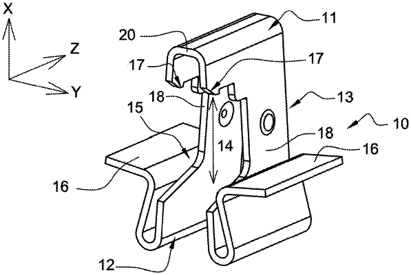
[ 21. A fastening staple formed of an electrically-conductive metallic part integrally made in one piece comprising:
a bearing head;
a counter-support foot;
a linking body linking the counter-support foot to the bearing head so that the bearing head and the counter-support foot are shifted from each other along a longitudinal direction (X) of the fastening staple by a determined interval;
wherein the determined interval between the bearing head and the counter-support foot is adapted such that the bearing head and the counter-support foot constitute a jaw,
wherein the counter-support foot comprises at least one bearing lateral flange positioned longitudinally,
wherein the bearing head comprises at least one hooking element,
wherein the counter-support foot comprises at least one mechanical tensioning flange capable of an elastic deformation and/or a displacement thereof, and said at least one mechanical tensioning flange is constituted by said at least one bearing lateral flange,
wherein the linking body is constituted by two lateral walls, shifted from each other in a lateral direction (Y) of the fastening staple and connected to each other at one of their longitudinal ends at the bearing head by a folding area, their opposite longitudinal ends being independent of each other at the counter-support foot, the counter-support foot including two separate portions disposed at said independent longitudinal ends of the two lateral walls, said two separate portions at said independent longitudinal ends being spaced apart from each other.]
|