| CPC G03G 15/0266 (2013.01) [G03G 5/0696 (2013.01); G03G 5/102 (2013.01); G03G 15/0216 (2013.01); G03G 15/0283 (2013.01)] | 17 Claims |

|
1. An electrophotographic apparatus comprising:
an electrophotographic photosensitive member;
a voltage application unit configured to cause discharge from an electroconductive member to the electrophotographic photosensitive member;
a charge transfer amount detection unit configured to detect a charge transfer amount per unit time resulting from the discharge from the electroconductive member to the electrophotographic photosensitive member; and
a charging potential control unit configured to control a charging potential of the electrophotographic photosensitive member,
wherein when V1 and V2 are defined by the following procedures (1) to (8) for the electrophotographic photosensitive member, the V1 and the V2 satisfy a relationship represented by the following expression (E-4):
100V1<V2−V1 (E-4), and
wherein the charging potential control unit is configured to control the charging potential of the electrophotographic photosensitive member at a time of image formation from a relationship between DC voltages at at least two points selected from a range in which an absolute value of a DC voltage applied by the voltage application unit is 700 V or more, and charge transfer amounts at the DC voltages at the at least two points:
(1) the electrophotographic photosensitive member is charged for 0.005 second;
(2) an absolute value of the charging potential obtained through measurement after 0.06 second from start of the charging in (1) is represented by Vd [V];
(3) the electrophotographic photosensitive member is charged for 0.005 second so that the absolute value of the charging potential becomes the Vd again after 0.18 second from the start of the charging in (1);
(4) exposure is performed with light having a wavelength of 805 nm and a light amount of 0.5 μJ/cm2 after 0.02 second from start of the charging in (3);
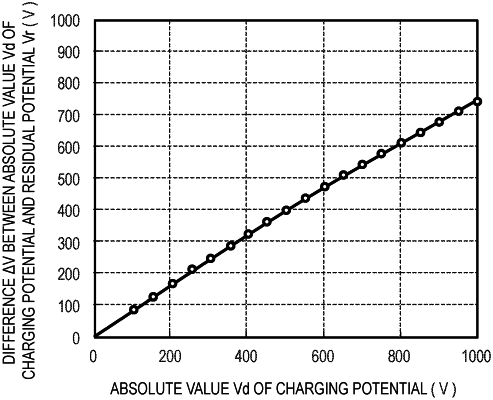
(5) the absolute value of the charging potential obtained through measurement after 0.06 second from the start of the charging in (3) is defined as a residual potential Vr [V];
(6) while the Vd is changed from 100 V to 1,000 V at intervals of 50 V, the procedures (1) to (5) are repeatedly performed to measure the Vr corresponding to each value of the Vd;
(7) a graph obtained by plotting the Vd and the Vr obtained in (6) with a horizontal axis representing the Vd and a vertical axis representing the Vr is approximated by the following equation (E-1) to determine constants A, “m”, and τ in the following equation (E-1):
 and
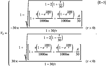
(8) voltages calculated by the following equations (E-2) and (E-3) through use of the constants A, “m”, and τ determined in (7) are defined as the V1 and the V2, respectively:
 in the equation (E-2), Vmin represents a numerical value determined by accuracy of the charge transfer amount detection unit.
 |