| CPC G01B 17/00 (2013.01) [G01N 29/04 (2013.01); G01N 29/44 (2013.01); G01N 2291/0234 (2013.01)] | 12 Claims |

|
1. A method for measuring a deviation angle of a fatigue microcrack based on nonlinear ultrasound, wherein the method comprises the following steps of:
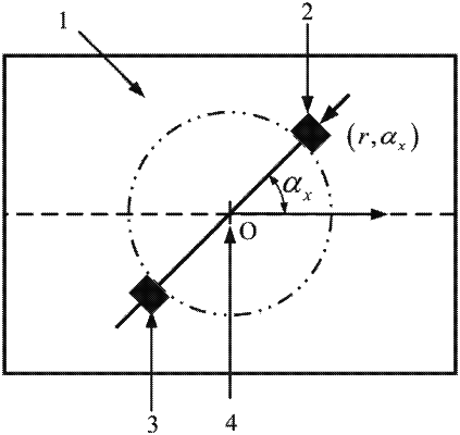
S1: preliminarily positioning a fatigue microcrack for a metal plate containing a microcrack defect to obtain a center O of the microcrack;
S2: taking the center O of the microcrack as an origin on a surface of the metal plate, selecting a direction as a horizontal positive direction, and taking a counterclockwise included angle of the horizontal positive direction as an orientation angle αx;
S3: drawing a positive circumference on the surface of the metal plate with the center O of the microcrack as a center of circle and r as a radius, and selecting an appropriate fixed interval angle Δα, wherein the orientation angle αx satisfies that αx=x·Δα, and 0°≤αx<360°; x is a number of change times of the orientation angle αx, and x=0, 1, 2, . . . , n; and n is a value limit of the number of change times x of the orientation angle αx,
 S4: placing an excitation sensor and a receiving sensor on the drawn positive circumference in the step S3 according to the orientation angle αx, wherein the excitation sensor is placed at the orientation angle αx, and the receiving sensor is placed at a place symmetrical with the orientation angle αx about the center O of the microcrack, and forming a group of ultrasonic sensing paths between corresponding excitation sensor and receiving sensor; sequentially increasing the number of change times x of the orientation angle αx, and changing positions of the excitation sensor and the receiving sensor to obtain n+1 groups of ultrasonic sensing paths; and ultrasonically testing each group of ultrasonic sensing paths, and recording time domain waveform signals formed by each group of ultrasonic sensing paths;
S5: converting each group of time domain waveform signals into a corresponding frequency domain graph, respectively extracting an ultrasonic fundamental wave signal amplitude A1x and a second harmonic waveform amplitude A2x in each group of frequency domain graph data, and calculating each group of relative nonlinear coefficients β′x, wherein the relative nonlinear coefficient is that
 and
S6: drawing an orientation angle αx—relative nonlinear coefficient β′x polar coordinate graph, wherein the drawn polar coordinate graph is an approximately symmetrical “leaf” pattern, an included angle between a vertical direction of a long axis of the approximately symmetrical “leaf” pattern and the horizontal positive direction is a deviation angle of the microcrack, and a range of the deviation angle of the microcrack is [0°, 180°); and
the orientation angle αx—relative nonlinear coefficient β′x polar coordinate graph takes the αx as a polar angle and the relative nonlinear coefficient β′x as a polar radius.
|