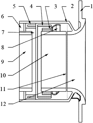
| CPC F04D 29/4206 (2013.01) [F04D 29/685 (2013.01); F05D 2220/40 (2013.01)] | 7 Claims |

|
1. An air intake bypass recirculation structure with adjustable air entraining amount and controllable broadband noise, comprising a main body of the air intake bypass recirculation structure and an air entraining amount adjusting structure, wherein:
an air intake bypass recirculation cavity is formed in the main body of the air intake bypass recirculation structure along a circumferential direction;
an air inlet of an air intake pipe and an air outlet of the air intake pipe are formed in two ends of an inner hole of the main body of the air intake bypass recirculation structure respectively;
an airflow inlet of the air intake bypass recirculation structure is formed in one side, closer to the air outlet of the air intake pipe than to the air inlet of the air intake pipe, of an inner side face of the main body of the air intake bypass recirculation structure;
an airflow outlet of the air intake bypass recirculation structure is formed in another side, closer to the air inlet of the air intake pipe than to the air outlet of the air intake pipe, of the inner side face of the main body of the air intake bypass recirculation structure;
the airflow inlet of the air intake bypass recirculation structure and the airflow outlet of the air intake bypass recirculation structure are both communicated with the air intake bypass recirculation cavity;
the air entraining amount adjusting structure is arranged in the air intake bypass recirculation cavity and located at the airflow outlet of the air intake bypass recirculation structure;
an air circulation area in the air intake bypass recirculation cavity is changed through the air entraining amount adjusting structure to adjust the air entraining amount of the main body of the air intake bypass recirculation structure;
an air intake adjusting structure comprises an annular valve and N intra-cavity airflow baffles with increasing diameters from inside to outside;
the N intra-cavity airflow baffles are coaxially sleeved in the air intake bypass recirculation cavity between an inner wall of the air intake bypass recirculation structure and an outer wall of the air intake bypass recirculation structure from inside to outside;
lengths of the N intra-cavity airflow baffles increase from inside to outside;
ends, away from the airflow outlet of the air intake bypass recirculation structure, of the N intra-cavity airflow baffles are flush and connected with an inner surface of an outer wall of the air intake bypass recirculation structure through baffle connecting columns;
the annular valve is sleeved in the air intake bypass recirculation cavity between the inner wall of the air intake bypass recirculation structure and the outer wall of the air intake bypass recirculation structure;
the annular valve is located at one side, closer to the airflow outlet of the air intake bypass recirculation structure than to the airflow inlet of the air intake bypass recirculation structure, of the N intra-cavity airflow baffles;
the inner surface of the outer wall of the air intake bypass recirculation structure is connected with sliding rails along the circumferential direction;
chutes respectively matched with the sliding rails are formed in an outer surface of the annular valve along the circumferential direction;
the annular valve is slidably installed on the outer wall of the air intake bypass recirculation structure through the sliding rails and moves along an axial direction through the sliding rails; and
N-1 annular slots matched with the intra-cavity airflow baffles are axially formed in one end, closer the intra-cavity airflow baffles than to a sealed mouth of the air intake bypass recirculation structure, of the annular valve.
|