| CPC F02C 7/10 (2013.01) [F05D 2220/32 (2013.01); F05D 2260/213 (2013.01)] | 12 Claims |

|
1. A gas turbine engine comprising:
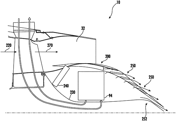
a compressor section, a combustion section, a turbine section, and an exhaust section in serial flow order and together defining a core air flowpath, the exhaust section including a primary exhaust flowpath and a waste heat recovery flowpath parallel to the primary exhaust flowpath; and
a waste heat recovery system comprising a heat source exchanger positioned in thermal communication with a first portion of the waste heat recovery flowpath,
wherein a first portion of an airflow that exits the turbine section during operation of the gas turbine engine travels through the primary exhaust flowpath,
wherein a second portion of the airflow that exits the turbine section during operation of the gas turbine engine is directed to the waste heat recovery flowpath,
wherein the waste heat recovery flowpath is inward of the primary exhaust flowpath in a radial direction, and
wherein the waste heat recovery system further comprises a valve disposed within a second portion of the waste heat recovery flowpath, wherein the valve is transitionable between an open position in which the second portion of the airflow flows to the heat source exchanger and a closed position in which the second portion of the airflow is restricted from the heat source exchanger, and wherein the valve comprises a rotatable guide vane.
|