| CPC F01D 5/141 (2013.01) [F05D 2240/307 (2013.01)] | 19 Claims |
|
1. A turbine blade comprising:
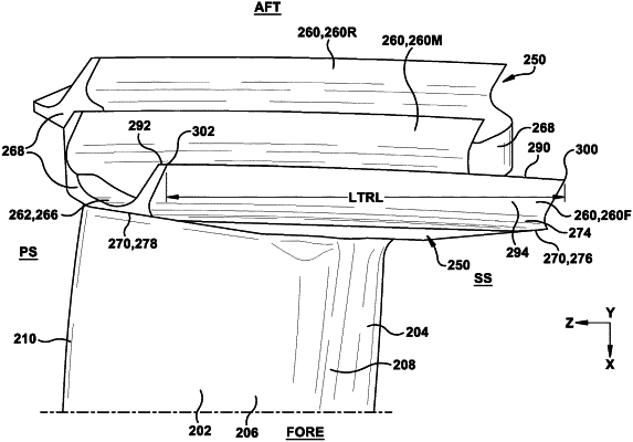
an airfoil having: a suction side, a pressure side opposing the suction side, a leading edge spanning between the pressure side and the suction side, and a trailing edge opposing the leading edge and spanning between the pressure side and the suction side; and
a tip shroud connected with the airfoil along the suction side, the pressure side, the trailing edge and the leading edge, the tip shroud including a forwardmost tip rail extending radially therefrom, the forwardmost tip rail having a forward edge including a suction side origin closest to the suction side of the airfoil and a pressure side origin closest to the pressure side of the airfoil, and a tip rail length defined by a straight line between the pressure side origin and the suction side origin,
wherein the forwardmost tip rail has a suction side scallop surface having a shape having a nominal profile substantially in accordance with Cartesian coordinate values of X, Y and Z set forth in TABLE I and originating at the suction side origin, wherein the Cartesian coordinate values are non-dimensional values of from 0% to 100% convertible to distances by multiplying the values by the tip rail length expressed in units of distance, and wherein X, Y and Z values are connected by smooth continuing arcs that are joined smoothly with one another to form the nominal profile that defines the suction side scallop surface.
|