| CPC E21B 4/14 (2013.01) [E21B 4/10 (2013.01); E21B 4/003 (2013.01)] | 18 Claims |

|
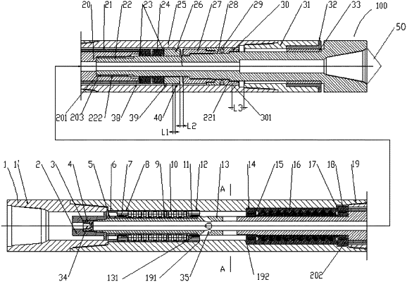
1. A drilling tool, comprising:
an outer cylinder;
a power rotary shaft arranged in an inner chamber of the outer cylinder and configured to be driven to rotate around an axis of the power rotary shaft;
a percussion generator arranged below the power rotary shaft, comprising:
a transmission shaft extending in the outer cylinder, and configured to be coupled with and driven by the power rotary shaft to rotate around an axis of the transmission shaft;
an output main shaft, which has an upper end engaged with a lower end of the transmission shaft so as to be driven by the transmission shaft to rotate about an axis of the output main shaft, and is movable relative to the transmission shaft along an axial direction; and
an percussion assembly, which is arranged between an annulus formed between the upper end of the output main shaft and the outer cylinder, and is configured to generate reciprocating impact along the axial direction on the output main shaft; and
a drilling bit connected with a lower end of the output main shaft extending out of the inner chamber of the outer cylinder,
wherein the percussion assembly comprises:
a cam anvil fixedly arranged around an outer wall of the output main shaft;
a cam hammer arranged around the outer wall of the output main shaft, a lower end of the cam hammer being formed with a driven tooth, which forms a conjugate set of cam teeth with a driving tooth formed on the cam anvil; and
an elastic member arranged in an annulus formed between the output main shaft and the outer cylinder and axially located between an upper end face of the cam hammer and a lower end face of the transmission shaft,
wherein during rotation of the cam anvil around an axis of the cam anvil, the driving tooth acts on the driven tooth to enable the cam hammer to move reciprocally in the axial direction and acts on the elastic member, so that the elastic member acts on the cam hammer and the cam anvil in sequence, causing the output main shaft to generate axial reciprocating impact, a wear-resistant joint is fixedly arranged at the lower end of the outer cylinder, and is in clearance fit with the output main shaft,
a retaining ring assembly is arranged around the outer wall of the output main shaft, and located below the cam anvil,
wherein the retaining ring assembly is configured to be in engagement with the wear-resistant joint, so as to prevent the cam anvil and the output main shaft from moving further downward relative to the transmission shaft,
wherein the retaining ring assembly comprises:
an upper retaining ring fixedly arranged around the outer wall of the output main shaft and located below the cam anvil;
a lower retaining ring arranged around the outer wall of the output main shaft, the lower retaining ring having an upper end face opposite to the upper retaining ring, and forming a locking connection between an inner wall of the lower retaining ring at a lower end thereof and a first step surface arranged on the output main shaft; and
balls arranged between opposing surfaces of the upper and lower retaining rings.
|