| CPC E03B 9/04 (2013.01) [G01L 19/086 (2013.01); Y10T 137/5456 (2015.04)] | 40 Claims |

|
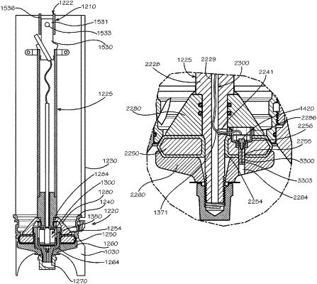
1. A fire hydrant comprising:
an upper barrel defining a cavity for fluid flow;
a lower barrel connected to a bottom of the upper barrel and defining a cavity in fluid communication with the cavity of the upper barrel;
a valve plate located in sealing communication with a lower end of the lower barrel;
a stem mechanically connected to the valve plate and configured to allow opening and closing of the valve plate, a top end of a lower stem of the stem comprising a sealing cap; and
a sensing assembly located within at least one of the cavity of the lower barrel and the cavity of the upper barrel, the sensing assembly comprising:
a sensor;
at least one battery in electrical communication with the sensor; and
an antenna in electrical communication with the sensor via a wire received within an interior cavity of the stem, the wire extending through the interior cavity from the sensor to the sealing cap, the antenna located inside the cavity of one of the upper barrel and the lower barrel and coupled to the sealing cap.
|