| CPC B60S 1/38 (2013.01) [C08G 18/10 (2013.01); C08G 18/163 (2013.01); C08G 18/1816 (2013.01); C08G 18/225 (2013.01); C08G 18/3206 (2013.01); C08G 18/4238 (2013.01); C08G 18/4854 (2013.01); C08G 18/7664 (2013.01); C08G 18/7671 (2013.01); C08G 18/775 (2013.01); C08L 75/04 (2013.01); B60S 2001/3829 (2013.01); B60S 2001/3836 (2013.01); C08L 2207/32 (2013.01)] | 10 Claims |

|
1. A vehicle windshield wiper blade, comprising:
a blade support portion; and
a lip portion swingably connected to the blade support portion via a neck,
the lip portion having a tapered portion a width of which, in a cross section in a direction perpendicular to a longitudinal direction of the wiper blade, gradually decreases from a side close to the blade support portion towards a direction farthest away from the blade support portion, and
the lip portion having:
a first tapered surface and a second tapered surface that constitute the tapered portion; and
a tip surface which, together with the first tapered surface and the second tapered surface, constitute a first edge and a second edge at a side of the lip portion farthest away from the blade support portion, and
wherien:
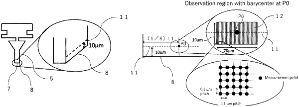
assuming that a first line segment is drawn on the first tapered surface parallelly to the first edge at a distance of 10 μm from the first edge;
a length of the first line segment is defined as L1;
points at (1/8)L1, (1/2)L1 and (7/8)L1 from one end side on the first line segment are defined as P0, P1 and P2 respectively; and
when measuring, using a scanning probe microscope, an elastic modulus at 70000 points at a 0.1 μm pitch in each of three rectangular observation regions on the first tapered surface, each of the rectangular observation regions having barycenter at P0, P1 and P2, and having a 70 μm-long side parallel to the first line segment and a 10 μm-long side perpendicularly intersecting the first line segment,
a mean value of the 210000 obtained elastic modulus values being 15 MPa to 470 MPa, and a coefficient of variation of elastic modulus being 17.6% or lower; and
assuming that a second line segment is drawn on the second tapered surface parallelly to the second edge at a distance of 10 μm from the second edge;
a length of the second line segment is defined as L2;
points at (1/8)L2, (1/2)L2 and (7/8)L2 from one end side on the second line segment are defined as P3, P4 and P5 respectively; and
when measuring, using a scanning probe microscope, an elastic modulus at 70000 points at a 0.1 μm pitch in each of three rectangular observation regions on the second tapered surface, each of the rectangular observation regions having barycenters at P3, P4 and P5 and having a 70 μm-long side parallel to the second line segment and a 10 μm-long side perpendicularly intersecting the second line segment,
a mean value of the 210000 obtained elastic modulus values being 15 MPa to 470 MPa, and a coefficient of variation of elastic modulus being 17.6% or lower.
|