| CPC B25B 15/04 (2013.01) [B25B 15/00 (2013.01); B25B 23/12 (2013.01); B25G 1/085 (2013.01)] | 8 Claims |

|
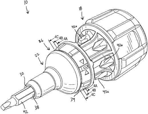
1. A screwdriver comprising:
a handle comprising:
a first end;
a second end;
an axis extending from the first end to the second end;
a body portion, the body portion including a plurality of openings extending through the body portion in a direction parallel to the axis and angularly spaced apart about the axis at a first position; and
a neck portion including an outer surface defining a diameter less than a diameter of the body portion, wherein the outer surface is a radially outward facing surface;
a shank coupled to the handle, the shank including a first end and a second end, the second end having a bore; and
a removable bit selectively positionable in the bore of the shank and within the body portion;
wherein the handle further comprises a rim positioned proximate the second end such that the rim is positioned between the shank and the body portion, wherein the diameter of the outer surface of the neck portion is less than a diameter of the rim;
wherein each of the openings is configured to support the removable bit such that a working end of the removable bit is positioned behind the rim, in a direction extending away from the shank; and
wherein, when the removable bit is positioned in one of the plurality of openings, the removable bit is coupled along the outer surface of the neck portion and radially external relative to the outer surface of the neck portion.
|