| CPC B21B 1/40 (2013.01) [B21B 13/02 (2013.01); B21B 2265/02 (2013.01)] | 3 Claims |

|
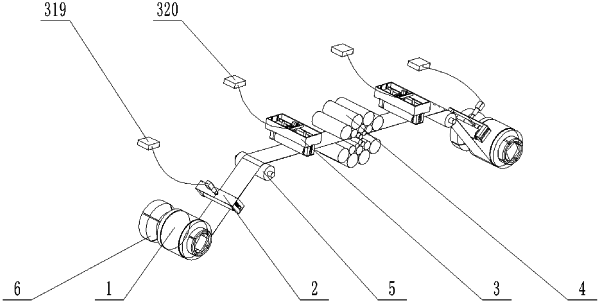
1. A semi-automatic adjustment device for suppressing tension fluctuations during a rolling process of an ultra-thin strip, comprising:
a coiler;
a tension roller;
a semi-automatic tension regulator, disposed between the coiler and the tension roller;
a twenty-high roller system; and
a semi-automatic tuned mass damper of variable stiffness and damping, disposed between the tension roller and the twenty-high roller system and comprising:
a damping assembly, comprising: a fixing shell, springs, telescopic rods, bearing seats, slots, a mass block and a pressure roller;
a semi-automatic variable stiffness assembly, comprising: an electromotor, a cover, a hydraulic pump, hoses, and an oil fluid;
a semi-automatic variable damping assembly, comprising: an electrical machine, racks, gears, conductor-concentrating flux plates and permanent magnets; and
a servo control assembly, comprising: a first acceleration sensor, a second acceleration sensor and a controller;
wherein the fixing shell is fixedly connected to the slots;
wherein the telescopic rods are respectively embedded in the springs, and an end of one of the springs is connected to the second acceleration sensor, another end of the one of the springs is fixedly connected to the mass block;
wherein two ends of the pressure roller are respectively provided with the bearing seats, and the bearing seats are respectively disposed at the slots;
wherein the permanent magnets arranged in two rows are symmetrically disposed on two sides of the mass block;
wherein the conductor-concentrating flux plates are symmetrically disposed on the two sides of the mass block;
wherein a side of each conductor-concentrating flux plate is a concentrating flux plate, and another side of each conductor-concentrating flux plate is a conductor baseplate; the conductor baseplates of the conductor-concentrating flux plates are disposed facing towards the permanent magnets and fixedly connected to the racks, and the racks are engaged with the gears, and the gears are connected to the electrical machine;
wherein an interior of the mass block is a hollow structure with the oil fluid, and the interior of the mass block is connected to the hydraulic pump through the hoses, the hydraulic pump is connected to the electromotor through the cover;
wherein the first acceleration sensor is disposed at a center position on an upper side of the mass block and configured to detect a vertical acceleration of the mass block, and the second acceleration sensor is disposed on one of the bearing seats and configured to detect a vertical acceleration of the pressure roller; the first acceleration sensor and the second acceleration sensor are connected to the controller through conducting wires;
wherein the controller is configured to: receive acceleration signals from the first acceleration sensor and the second acceleration sensor, and process the acceleration signals to obtain instantaneous vibration frequencies of the mass block and the ultra-thin strip through Hilbert-Huang transformation algorithm; and control, in response to the instantaneous vibration frequencies of the mass block and the ultra-thin strip being inconsistent, the electrical machine and the electromotor to work individually;
the controller is specifically configured to: change a distance between the conductor-concentrating flux plates and the permanent magnets, thereby to change a magnitude of eddy current damping control by driving the electrical machine to work to drive the gears to rotate and the racks to move along a same direction or reverse directions, and the magnitude of the eddy current damping is capable of being adjusted in real time to achieve an optimal vibration energy dissipation effect; and
the controller is specifically configured to: change stiffness of the semi-automatic tuned mass damper of variable stiffness and damping by driving the electromotor to work to drive the hydraulic pump to adjust an amount of the oil fluid in the mass block.
|