| CPC A61M 5/3202 (2013.01) [A61M 5/178 (2013.01); A61M 5/3216 (2013.01); A61M 5/34 (2013.01); A61M 2205/273 (2013.01)] | 1 Claim |

|
1. A device for adjusting the tightening angle of a needle safety protector, the needle safety protector having a reuse prevention structure, the device comprising:
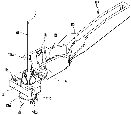
a needle hub (101); and
a needle safety protector main body (102) and a cover (103) connected integrally with the needle safety protector main body (102) to be foldable thereto,
wherein the device is configured such that, with the needle hub (101) tightened to the needle safety protector main body (102), a Luer-lock coupling protrusion (105a, 105b) of the needle hub (101) and a Luer-lock screw portion (108) formed at a front portion of a barrel (107) are tightened to each other so that injecting is performed while the barrel (107) and the needle safety protector main body (102) are coupled integrally to each other, and an injection needle (104) is covered with a needle cap (106), and the cover (103) is folded to the needle safety protector main body (102), and
on an inner circumferential surface of a hub coupling hole (110) vertically formed at a center portion of the needle safety protector main body (102), tooth protrusions (114a) formed in semicircles on a plan section are arranged at equal intervals in a circumference of the hub coupling hole (110), and on a body surface of the needle hub (101) fitted in the hub coupling hole (110), tooth protrusions (114b) formed in semicircles on a plan section are arranged at equal intervals in a circumference of the needle hub (101), so that the needle hub (101) is tightened to the needle safety protector main body (102) with the tooth protrusions (114a) formed along the hub coupling hole (110) and the tooth protrusions (114b) formed on the body surface of the needle hub (101) alternately engaged with each other,
wherein a hub sliding flange inserting groove (115) is formed on a circumference of the hub coupling hole (110) at a lower surface of the needle safety protector main body (102), and a stopper (118) is formed by protruding on a point of a sliding flange (117) formed at a rear circumference of the tooth protrusions (114b) of the needle hub (101), wherein an inner diameter of the hub sliding flange inserting groove (115) expands by a protruding length of the stopper (118) in order to insert the stopper (118) into the hub sliding flange inserting groove (115), and stopper locking steps (116a and 116b) are formed on both left and right sides of the hub sliding flange inserting groove (115) to prevent the needle hub (101) from being rotated more than half of the circumference to the left and right.
|