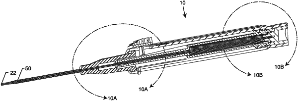
| CPC A61M 25/0693 (2013.01) [A61M 25/0023 (2013.01)] | 12 Claims |

|
1. A catheter insertion device, comprising:
a hollow needle having a distal skin-piercing end opposite a proximal needle end, the hollow needle defining a channel in fluidic and/or pneumatic communication between the distal skin-piercing end and the proximal needle end;
a needle base, wherein the proximal needle end is attached to the needle base;
a plunger slidably disposed over at least a portion of the hollow needle, wherein the distal skin-piercing end of the hollow needle extends through a plunger distal end, the plunger having a plunger proximal end opposite the plunger distal end;
a compression spring disposed concentric with and over at least a second portion of the hollow needle, the compression spring mechanically engaged directly and/or indirectly between at least a portion of the needle base and a portion of the plunger, the compression spring biasing the plunger away from the needle base;
a catheter slidably disposed over at least a third portion of the hollow needle, wherein the distal skin-piercing end of the hollow needle extends through a distal insertion end of the catheter, the catheter comprising the distal insertion end opposite a proximal connection end, wherein a catheter surface is configured to be contactable by the plunger distal end when the plunger moves in a forward direction;
an expandable chamber in fluidic and/or pneumatic communication with the channel of the hollow needle by an aperture in the needle base, the expandable chamber at least partially delimited by the needle base and the plunger proximal end, wherein the expandable chamber is configured to increase in volume as the plunger moves towards the distal skin-piercing end of the hollow needle;
wherein a longitudinal axis is defined as extending along the hollow needle, the needle base, the plunger, the compression spring and the catheter, wherein the plunger is configured to move between a stored position, an armed position and an extended position, wherein the plunger at least rotates about the longitudinal axis between the stored position and armed position, and wherein the plunger at least translates along the longitudinal axis between the armed position and the extended position;
a generally hollow housing, wherein the needle base, the plunger and the compression spring are at least partially disposed within the generally hollow housing in the stored position;
a first circumferential seal of the expandable chamber disposed between the needle base and the plunger, the first circumferential seal configured to seal the needle base to the plunger for a distance when the plunger moves away from the needle base;
a second circumferential seal of the expandable chamber disposed between the plunger and the generally hollow housing, wherein the second circumferential seal is configured to seal the generally hollow housing to the plunger for the distance when the plunger moves away from the needle base; and
wherein the generally hollow housing includes an annularly-shaped seal relief formed as an inside surface of the generally hollow housing, wherein the second circumferential seal in the stored position is aligned along the longitudinal axis with the annularly-shaped seal relief where the second circumferential seal is not in contact with the inside surface of the generally hollow housing.
|