| CPC H02J 3/381 (2013.01) [H02P 21/22 (2016.02); H02S 40/32 (2014.12); H02S 50/10 (2014.12); H02J 2300/26 (2020.01)] | 2 Claims |

|
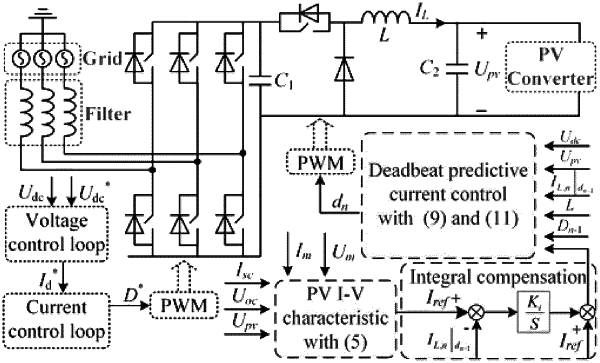
1. A fast-response PV simulator based on an improved deadbeat predictive current control (DPCC), comprising a reference value calculation module, a DPCC controller and a modulation control module, wherein the reference value calculation module is implemented through a PV array model, the PV array model collects the output voltage Upv in real time, and combines with the set voltage of maximum power point Um, the set current of maximum power point Im, short-circuit current Isc, and open-circuit voltage Uoc to calculate the reference value of the output current Iref,
the DPCC controller receives the calculated reference current value and derives the deadbeat control law for the inductor current by formulating the discrete model of the power electronic converter; it inputs the collected direct current bus voltage Udc, output voltage Upv, the current inductor current IL,n+1|dn+1, inductor value L, the previous moment's duty cycle dn−1 and the reference value of current Iref into DPCC controller to obtain the reference value of duty cycle for the next moment dn;
the calculated reference value of duty cycle dn is automatically updated at the start of the next moment; the modulation control module obtains the triggering signals for the Insulated Gate Bipolar Transistor (IGBT) through the modulation sector; after passing through the drive circuit, it performs real-time control of the IGBT, enabling the output current of the fast-response PV simulation to track its reference value;
the implementation steps of the DPCC controller are as follows:
(1) equivalent DC-DC topology of the fast response PV simulation
the DC-DC topology of the fast-response PV simulator can be equivalent to a buck converter for analysis; when the DPCC strategy is used in the DC-DC converter, the inductor current must be accurately modeled to obtain the correct predicted value of the control variable;
when the switch tube is on, the expression of the inductor current is as follows:
 where L is the inductance value of the buck converter, IL1 is the value of the inductor current, Uon, is the output voltage of the buck converter, and Udc is the input voltage;
when the switch tube is off, the expression of the inductor current is as follows:
 where Uoff is the output voltage of the buck converter, and IL2 is the value of the inductor current;
when the buck converter works in a steady state, the energy of the inductor is balanced between absorption and dissipation during a single switching period. Due to the short duration of a single switching period, the output voltage is considered constant during this interval; therefore, the output voltage of the switch tube does not change in a single switching period, as follows:
Uon=Uoff (3)
(2) accurate modeling of inductor current in fast response PV simulation
assume that the value of the inductor current at time tn is IL,n; if the duty ratio at time tn is the same as that at time tn−1, then, at time tn+1, the calculation expression for the value of the inductor current is as follows:
 where dn−1 is the duty ratio at time tn−1, IL,n+1|dn+1 is the value of the inductor current at time tn+1 when the duty ratio is dn−1, and Ts is the switching period of the buck converter;
when the duty ratio changes to dn at time tn, the value of the inductor current at time tn+1 is expressed as IL,n+1|dn;
(3) control law of DPCC
the relationship between IL,n+1|dn and IL,n+1|dn+1 is as follows:
 equation (5) shows that if the duty ratio changes from dn−1 to dn at time tn, then, at time tn+1, the value of the inductor current will change to IL,n+1|dn, consequently, if the reference value of the inductor current is equal to IL,n+1|dn, the DPCC of the inductor current can be realized; therefore, the DPCC law for the DC-DC topology of the fast-response PV simulator can be presented as follows:
 where IL,n+1|ref is the reference value of the inductor current at time tn+1.
|